Feb 2018 Edit
@madcowswe has pointed out that measuring the winding temperature rise when the motor is completely stationary may not be the best reflection of real world use since the windings will be heated unevenly. Also there was nothing scientific about the thermocouple placement. I just jammed it in and hoped for the best. So when interpreting the temperature measurements keep these points in mind.
Hey Everyone
I have made some measurements of static motor torque and temperature rise for anyone interested. The motor I tested is a Keda 190 KV 6364 from hobbyking.
Static Torque
Static torque was measured by bolting a leaver to the motor and measuring the force generated at 0.35 m with a kitchen scale when the motor was commanded to rotate into the scale. The current was limited in firmware and adjusted for the known 675/500 offset.
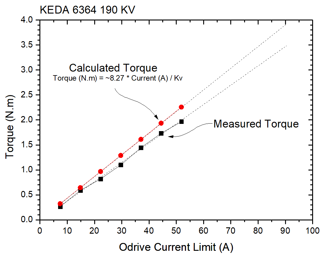
The measured torque tracks fairly well with the calculated torque based on the motor Kv. The ~15% overestimation may indicate that the motor Kv is a bit higher than that stated by Hobbyking. I have yet to measure the Kv to check if this is the case or not. Either way this results shows that the calculated torque is indeed a good estimation of the real thing.
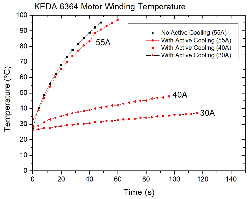
Motor Temperature
I tested the motor winding temperature rise at 30A, 40A and 55A by inserting a thermocouple into the windings of the motor. I also tried to improve the cooling of the motor by directing a fan onto it.
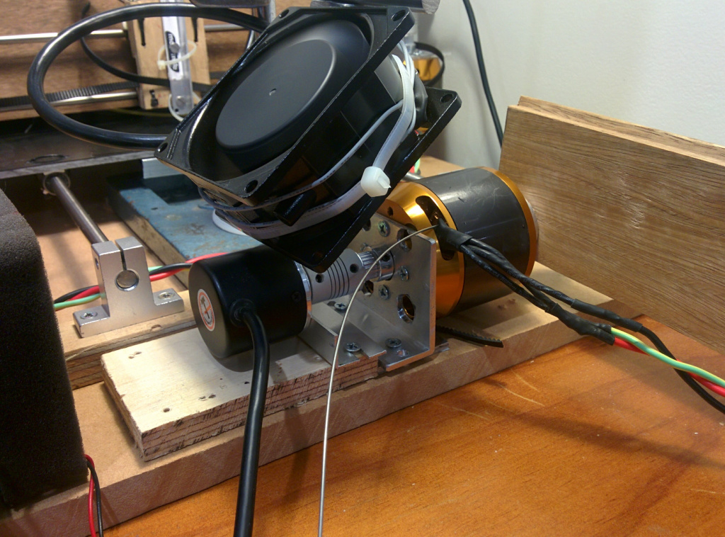
Here is the cooling setup. The thermocouple is the rod entering the motor near its winding leads.
Two things are quite clear. 1. Temperature rise is non-linear with increasing current as expected for a resistive load (Joule heating) and 2. Adding a fan didn’t help that much with cooling.
If your planning on using the odrive to hold a static load you should also consider the temperature rise of the mosfets which I have also measured with a couple of different cooling options.
MOSFET temperature rise
I measured the MOSFET package temperature with two small thermocouples (0.1mm bead) for a good temperature response and at a static current of 55A. One thermocouple was attached to the top of a MOSFET package with thermal compound while the other was soldered to a thermal via under the collection of MOSFET packages.
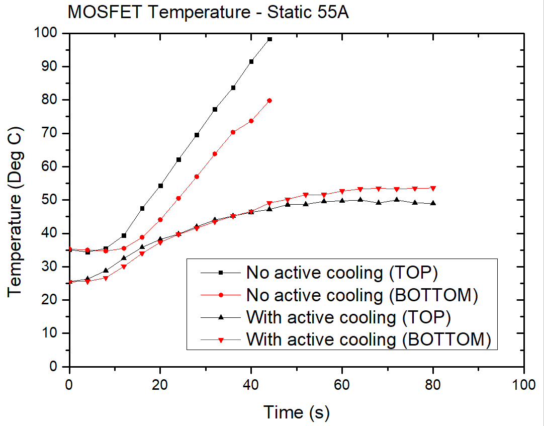
You can see that provided you have a fan on the MOSFETS then they don’t get too hot and two values agree fairly well between the two measurement positions. Being able to measure the temperature from under the board also allowed the influence of a heatsink attached with thermal compound to be tested.

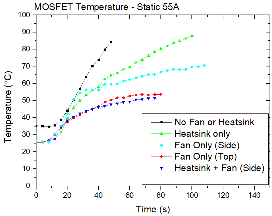
Here its clear that just having a heatsink without a fan is not ideal at these current levels. I also tested the effect of placing the fan above the boards and next to the boards (blowing across it) which is a more realistic setup when you have multiple boards stacked on top of each other in an enclosure. Obviously the best setup is a fan and heatsink. However at this current value you could probably just get away with just a fan since your motor will likely overheat long before your MOSFETs do. However if you are running a bigger motor, a motor with powerful cooling or in a hot enclosure then a heatsink and fan is probably a good idea.