tldr: Using a 60mm server fan to force air through the windings of your motor will allow you to considerably increase the usable holding torque of your motor without it overheating.
Hey everyone
I plan on using some 5060 BLDC motors with a big CNC router that I am building. However I know from testing some bigger motors that you can not use anywhere near the ‘rated’ current of these motors without them quickly overheating. Therefore I wanted to see how effective forced air cooling is at keeping the motor temperatures within safe limits while at high currents.
The Setup
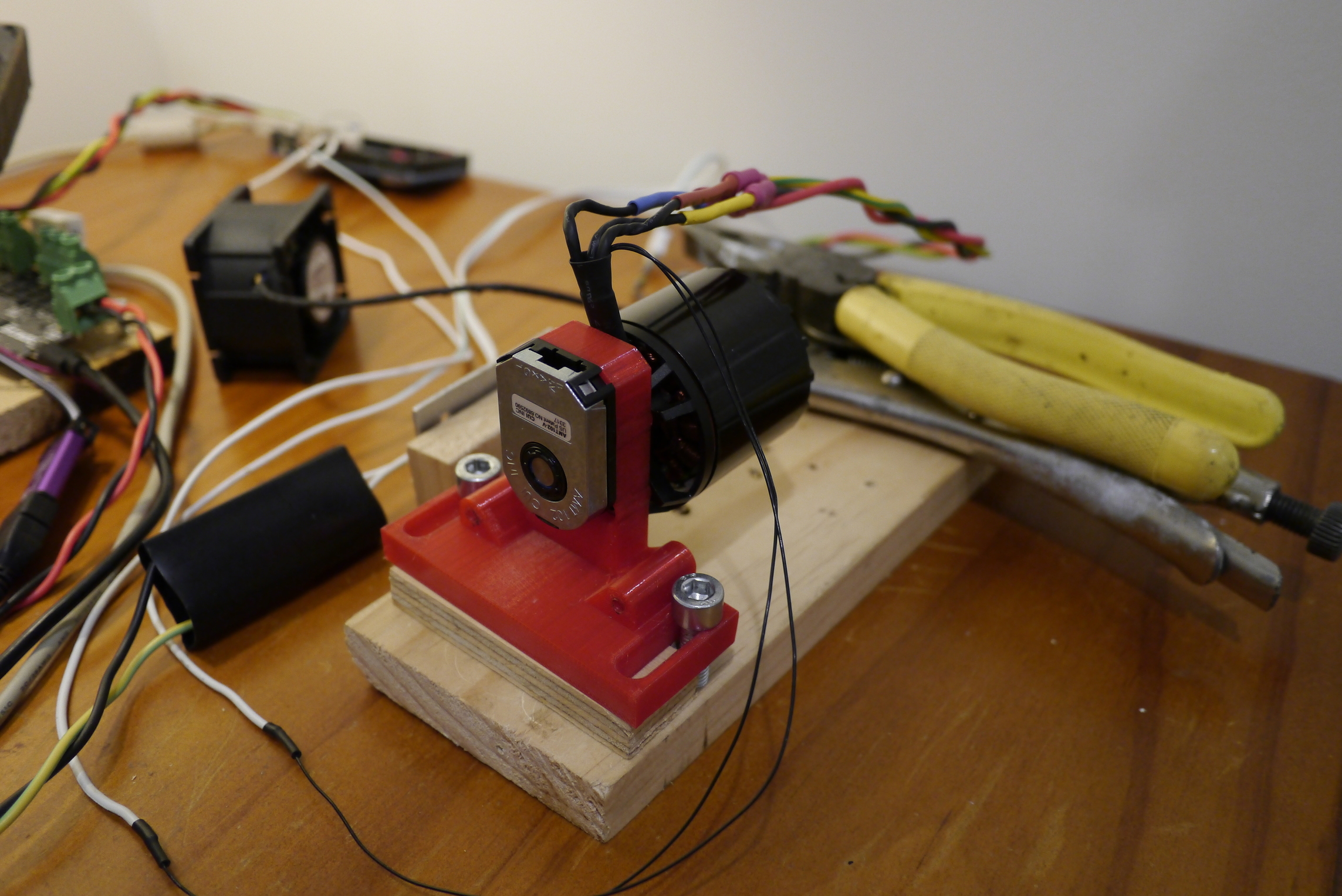
A N5060 270 Kv ‘80A’ motor with embeded thermistors was used. The thermistor has been epoxied between the windings of the motor which ensures good thermal contact. The motor was heated by setting it to search for an index pulse with the encoder disconnected (thanks @madcowswe for that suggestion!) and then setting the .calibration_current to 40A. The benefit of this method over just locking the shaft and commanding it to a far away position is that with the motor turning all three phases are used equally which is more representative of real world use. The fan is a 60mm, 38 mm long 12V 1.68A server fan, costed $3.12 USD and was purchased from here. The duct and mount was designed in fusion 360 and is setup so that the fan blows cool air through the motor from the face plate side and hot air exist at the back. You can find a copy of the CAD files for the mount and shroud here.
Note that I am also using a fan to cool the odrive board itself as you will risk overheating if held at 40A for minutes at a time.
The motor was tested naked (no fan or duct), with the fan pointing so that air flows over it from the side and with a duct attached to the motor to direct the air through its windings.
Stand alone motor
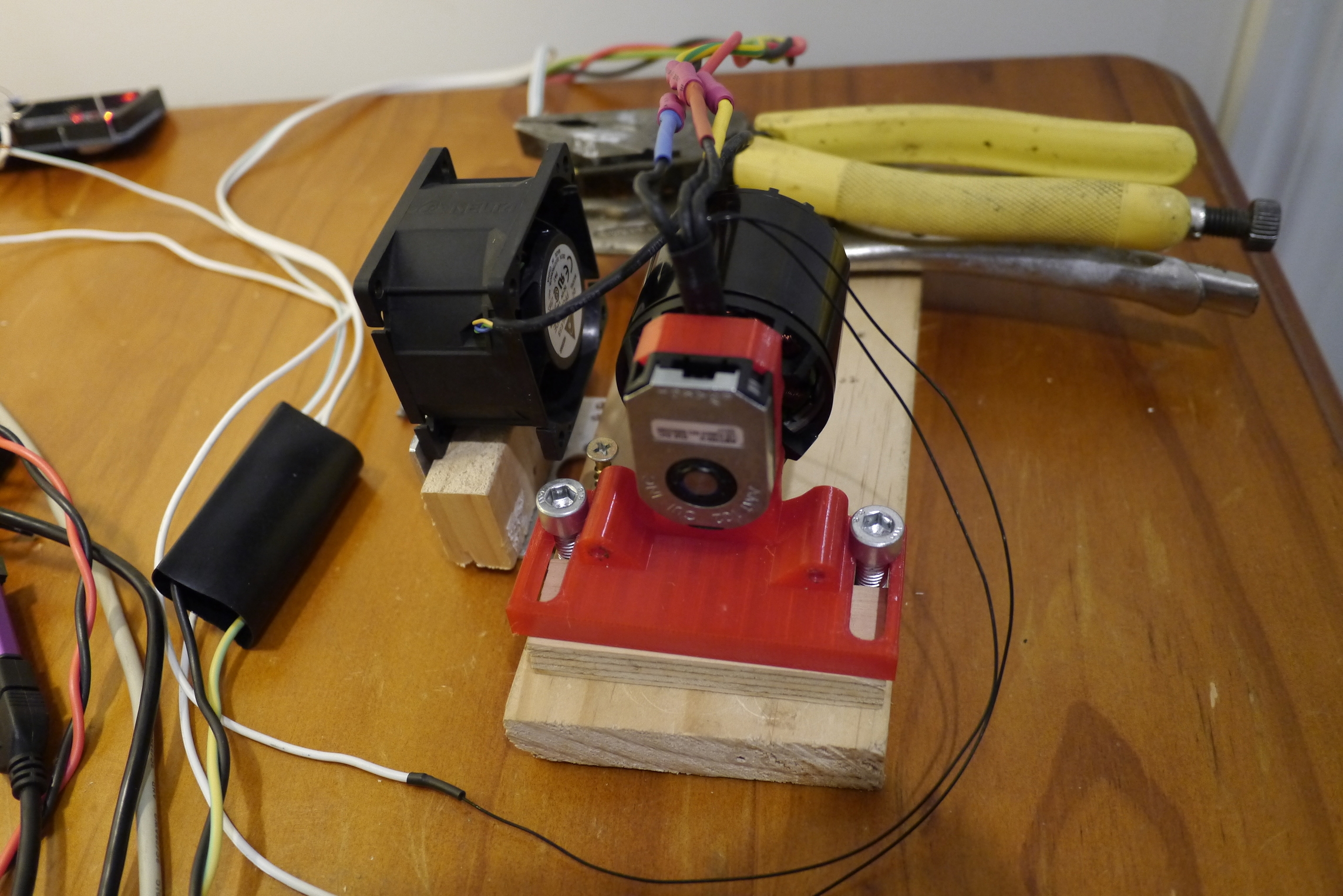
Fan from the side.
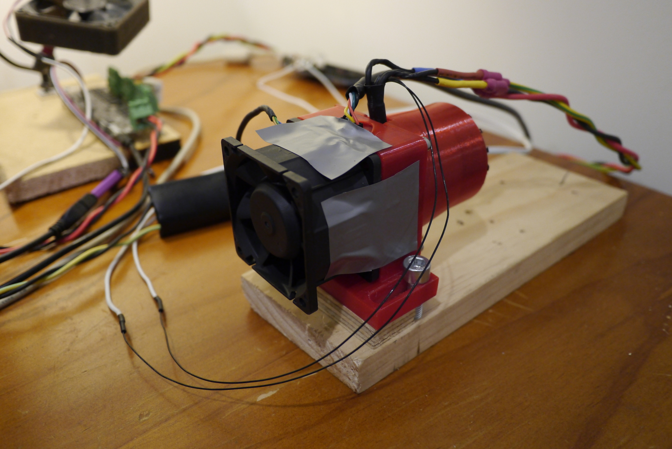
With duct.
The Results
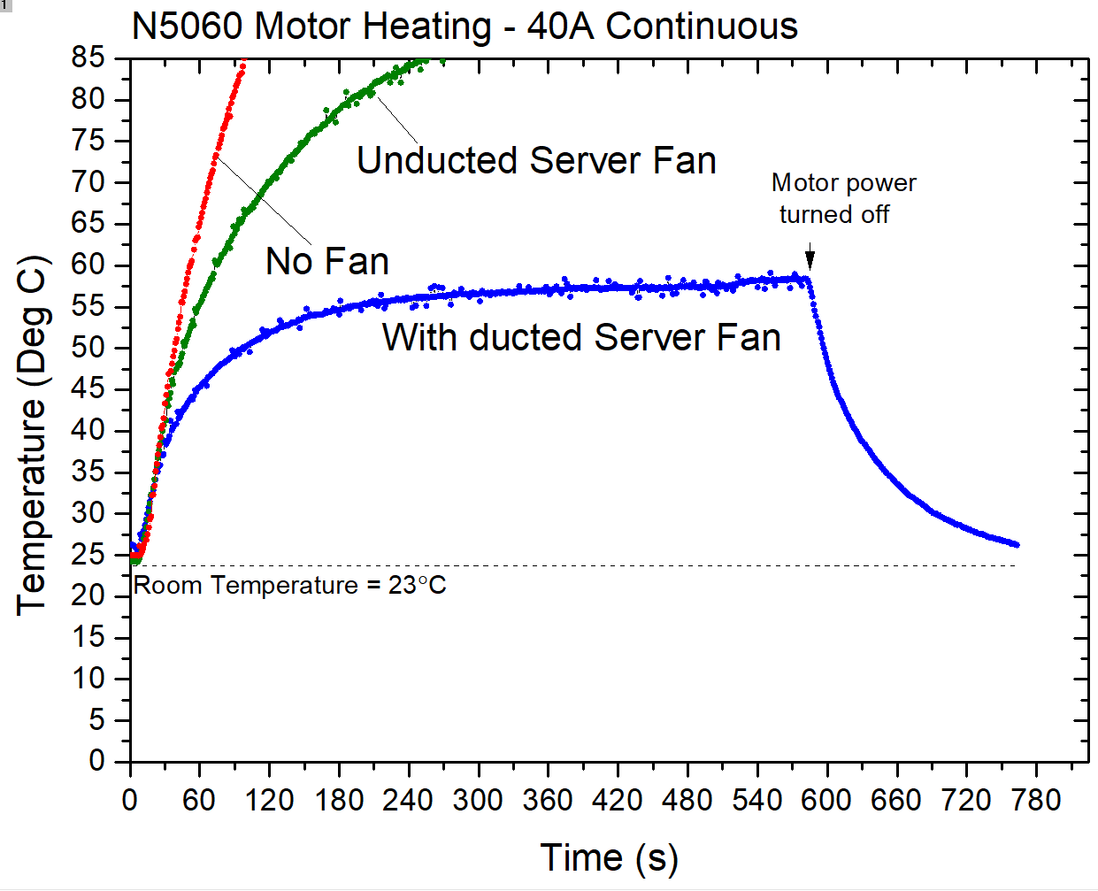
- No fan: The temperature shoots off for the moon.
- Fan from the side: The temperature rises more slowly but still reached 85C in short order and looks like it would have continued to much higher temperatures than that.
- Ducted fan: Temperature stabilises around 60C.
I consider this result a success and plan on using such a setup with my CNC router with appropriate mesh filters fitted. I plan on milling aluminium mostly so fine particulates are less of an issue and the motors will be well shielded from the work area. From the results it also looks like there is still some head room to increase the current further if needed with the ducted setup.
The downside is of-course that the fan adds a lot of noise to the setup.
This is not such an issue for a CNC router since it will be just as noisy but its way too load to consider using in a quiet room. Of course you can also tie the fan speed to the temperature of the motor which is what I plan on doing for my CNC router using a microcontroller to monitor the thermistor and the PWM input of the fan to control its speed. That way it will only come on (and ramp according) when needed.