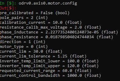
I have an Odrive board V3.6 56V, a 1300kV 4Poles 4092 motor, a 3S3P li-ion battery (30A) and a AS5047P magnetic encoder 4096cpr.
I have used dfu-util on windows to update firmware to fw-v0.4.1. Ok
My calibration sequence is OK.
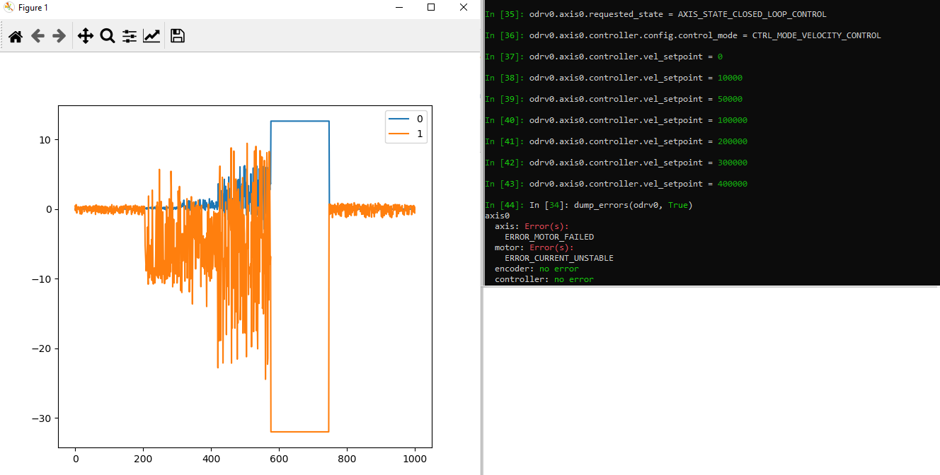
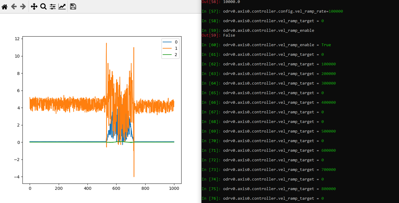
I can make the motor turn with position mode when vel-limit is low (less than 300000) but it stops when allowing him to run faster. See below.
In [41]: odrv0.axis0.requested_state = AXIS_STATE_CLOSED_LOOP_CONTROL

In [42]: odrv0.axis0.controller.pos_setpoint = 100000

In [43]: odrv0.axis0.controller.pos_setpoint = 0

In [44]: odrv0.axis0.controller.config.vel_limit=100000

In [45]:  odrv0.axis0.controller.pos_setpoint = 0

In [46]:  odrv0.axis0.controller.pos_setpoint = 100000

In [47]:  odrv0.axis0.controller.pos_setpoint = 0

In [48]: odrv0.axis0.controller.config.vel_limit=200000

In [49]: odrv0.axis0.controller.pos_setpoint = 100000

In [50]: odrv0.axis0.controller.pos_setpoint = 0

In [51]: odrv0.axis0.controller.config.vel_limit=300000

In [52]: odrv0.axis0.controller.pos_setpoint = 100000

In [53]: odrv0.axis0.controller.pos_setpoint = 0

In [54]: odrv0.axis0.controller.config.vel_limit=400000

In [55]: odrv0.axis0.controller.pos_setpoint = 100000

Motor stopped here

In [56]: dump_errors(odrv0, True)
axis0
  axis: Error(s):
    ERROR_MOTOR_FAILED
  motor: Error(s):
    ERROR_CURRENT_UNSTABLE
  encoder: no error
  controller: no error
axis1
  axis: no error
  motor: no error
  encoder: no error
  controller: no error
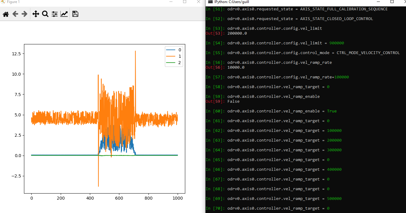
I can make the motor reach high speeds with slow ramp when using velocity control.
but when ramp become high or disabled it stops with the same error.
First, I am one of those mech guys trying to understand electrical things…
I am thinking that this article is pointing the truth : First track Second track
Looking at the specs of your motor, I would think odrv0.axis0.motor.config.current_lim is too low.
Separately, I had similar issues with a 2830 motor even after raising current_lim and lowering pos_gain mentioned here has eliminated this error for me.
From what i understand, the motor current has the time to rise between two consecutive pulses because we can’t account on a relative low inductance of the motor to “smooth” the current…
I tried to find 100µH inductor to put in serie, but my motor is rated at 110A and it seems that it’s way above 100µH inductor capabilities…
@Neil_FV, i think you had a similar problem with an inductance of 5.10^e-6 Henry. Did you solve it ?
It seems there is a minimum inductance to respect so as to use Odrive.
its been about 6 months since I last did any work on this project (slipped down in priority) so I’m a bit hazy. I can tell you that we were able to hit the high speed we required and that these are my settings…
After few searchs it seems that there is a minimal inductance to respect in order to use Odrive. You can calculate the approximate value you can use with :
Min Inductance L = 0.6*(VBus/(fPWM*I nominal)) [Henry]
Vbus : Power Supply V
fPWM : 24000 Hz for Odrive
I nominal : expected working current A
In my case : 0.6*(12/(2400020)) => 15µH
Note that at no load (let say 1A) => 300µH
My motor is 4µH so I have just bought 3 (20A, 15µH) inductors to put in serie to test. It should be ok with load but could be unstable at no load.
Ripple current in A car be calculate as follow :
Ripple = (Vbus/R)(1-e(-R/(2L*fPWM)))
R : phase resistance of the motor (ohm)
L : phase inductance (Henry)
In my case : 12/0.016*(1-e(-0.016/(20.00000424000))) = 60A… it explains the noise…
Ok, that’s why it’s working. Here are the solutions I have found :
" Dynamic information:
The electric time constant of this motor is too low. First of all, if not done yet, try setting the PWM Frequency to the highest possible. Then, try the following options…
Option 1:
If you are not willing to move the motor at its maximum speed, reducing the bus voltage could help overcoming low inductance problems.
Option 2:
If current/torque control is not required, bypassing it could work like a charm to avoid instabilities caused by low inductance effects.
Option 3:
If the working state is with higher friction or inertial load attach, it will probably be controllable in that case. @Neil_FV : your case.
Option 4:
Place an in series phase to phase inductor"
@Wetmelon, hi, is option 2 achievable ? I mean, I do not know if bypassing it for low inductance could be a software option ?
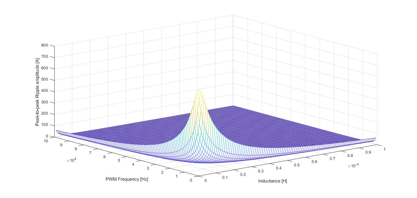
Here is the Ripple surface for 5KHz to 100Khz PWM with 0.016Ohm phase resistance, 12V of supply and inductance from 1µH to 300µH. We can see that both high Inductance and high PWM can avoid you to be in the “hell corner”…
According to theory, phase inductor should raise to 19.5µH and Ripple to 13A, still a lot…
After calibration we have the real values : 22µH and 0.0189Ohm : consistent
With real values we expect 11.3A of Ripple : still too much.
And as you can see, value are very consistent !
Conclusion : Low inductance motors (let’s say under 200µH) can be control but they need special care talking about : Supply Voltage (low if possible) , PWM frequency (higher if possible), and inductance (higher if possible), playing with physical load or current control loop could help.
Hi everyone, I have a good control of my “very low inductance motor” with odrive despite the “low” PWM frequency. Here are the things you have to understand :
PWM frequency can’t be higher because of the hardware. (I did change it with sucess but cpu can’t do the job).
Tip 1 : I add the 3 phase inductors to limit as much as possible the ripple current.
Tip 2 : you have to use trapezoidal trajectory planner for your everyday moves, you’ll then be able to control these parameters :
Limiting accel_limit and decel_limit to a real world value will avoid you to force the control loop to ask for a “far too big value”. Thus you will limit the inrush current in the windings and it will avoid you to trigger “ERROR_CURRENT_UNSTABLE”.
Tip Bonus : Morevover, I did noticed that you can overcharged your braking resistor (check datasheet) by a factor of 10 or more for a short time. It is the case in my application (burst). You have to change the value in ohm in order to trick the controller.
Thanks Guis, I ran in to an overvoltage tonight when rapidly switching directions on my motor. I have a question. When you say “You have to change the value in ohm in order to trick the controller.”, how much do you change it? Earlier you say a factor of ten or more, but that must be burst power. The odrive docs do say you can change the value in ohm but no more than 50% over. That wasn’t enough for me though. How much over have you done yours?
@tlalexander what is the precise error you had ? The acceptable overload of a resistor depends on the specific resistor and only concern braking power dissipation.
Here are examples :
The Short Time Overload is 5 x rated power for 5 s.
Pulse and Overload Performance graphs show us that between 0.1 and 1s you can expect 10 x rated power.
I don’t know what your project is but think about that :
In certain projects, like skateboard, braking is a big thing and overload can’t be accepted, in actuation (linear electric actuator), it can be true for example when you want to slow down a mass falling with gravity (lifting equipement) . But in other projects, it’s only a matter of peek overload while reversing direction or suddenly stopping the movement.
In my specific case I do use between 10 (0.2ohm) and 20(0.1 ohm) ratio instead of 1(2ohm) without problems but my project is very continuous and i only need it for a quick burst of 0.2s each 1.5second.
Well my resistor is just several meters of 26 gauge magnet wire. I’m not worried about damaging this resistor, but I am concerned about running too much current through whatever FETs feed power in to the brake resistor.
I am actually driving a brushed motor on phase bridges B and C with custom firmware. When I try to rapidly reverse the motor I get a rise in voltage to 60v (as confirmed at the braking resistor on an oscilloscope). I am testing a worst case reversal situation and will use trapezoidal planning in the final application, but I want to get a little more headroom on motor reversal.
So you use a 2 ohm resistor and you set the brake resistor value in firmware to 0.2 ohms? Or the other way around? Thanks!
EDIT: Well the issue was my code. I am adding brushed motor support but I did not update ictrl.Ibus, which is needed by the brake resistor code to function properly. Once I updated my motor drive code to update ictrl.Ibus, the brake resistor works as expected again.
@tlalexander So you use a 2 ohm resistor and you set the brake resistor value in firmware to 0.2 ohms? Correct. Even 0.1.
“running too much current through whatever FETs feed power in to the brake resistor” I suppose the FET can handle the same current as one phase ?? I mean if Odrive is able to work with such amps on one phase, it can put it on a resistive load.
About your edit : Cool ! Without the need to change resistor value ?
Correct. My code essentially failed to utilize the brake resistor because of the new motor control function I am using. The brake resistor had no effect because of a bug, and that’s why I was getting overvoltage. Once I updated the code it started working. Thanks for the reply!
That should result in 1/10th of the current, not 10x. V = IR, and the brake resistor fixes R and I in this calculation so V will be 1/10th of the size, resulting in 1/10th of the current. If you want to overdrive your brake resistor by 10x, use a value of 20. That being said, the new logic is much better at clamping the voltage. I recommend simply setting the brake resistance to the value you actually have now


 I did not work a lot on this particular point once I noticed correct working.