I’m looking for some help concerning the calibration of the brake resistor on my Odrive.
I’m using a v3.6 24v ODrive, powered with a 24V transformer.
I’m using hub motors (link), and went through the hoverboard calibration.
The goal of my installation is to move a 400kg load (with two motors), forward and backward on a couple of meters, at a speed of around 15cm/s, and my intuition tells me that the braking phase could be problematic if not managed properly.
That’s why I recently tried to adjust the braking settings. I plugged the resistor supplied with the odrive, set odrv0.config.enable_brake_resistor to True, and checked that odrv0.config.brake_resistance = 0.5. I also checked the odrv0.config.max_regen_current and odrv0.config.dc_max_negative_current, but I’m not quite sure what to do with these parameters. Should I just set them to 0 since I’m not using batteries as a power supply ?
After adjusting these settings, I tried once again to go through the hoverboard calibration, and as soon as I sent the command odrv0.axis0.requested_state = AXIS_STATE_MOTOR_CALIBRATION, I heard kind of a spark, and I lost the ODrive. Since then, I can’t connect to the ODrive anymore, the power led won’t turn on when powered, and I can hear some sort of sizzling (probably from the STM32).
Has anyone experienced the same issue ? Am I doing something wrong or missing something ?
Thank you in advance, I’m quite new to all of this and any help woud be a big step for me !
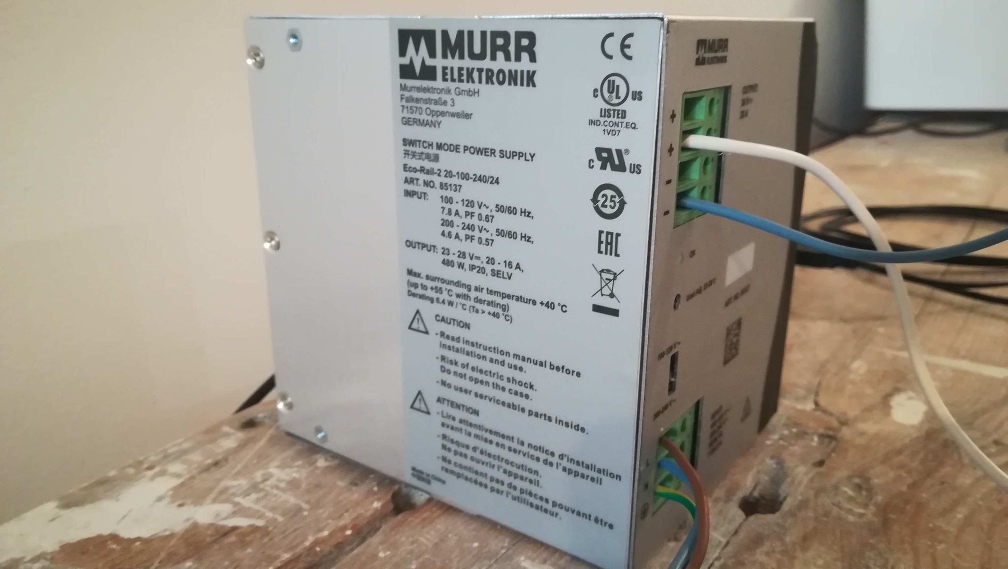
When you say ‘transformer’, do you mean an actual lump of iron with two windings, a bridge rectifier and a big capacitor? Or do you mean an AC-DC switching power supply?
A 24V transformer will output a lot more than 24V when there is very little current flowing, and this could easily damage the ODrive.
Even if you are using an AC-DC converter, these sometimes output a little more than their rating, and 24V is the absolute max DC Bus voltage that the 24V ODrive can handle, even for a short time.
For that reason, the 24V ODrive is not really suitable for use in a 24V system in my opinion (especially with high inertia loads!), because the tiniest overvoltage can kill it.
If possible I would use the 56V ODrive in this application.
Definitely set dc_max_negative_current to 0, or -0.01 to avoid spurious trips.
It’s likely that one of the MOSFETS has failed short circuit, since these are the limiting component on the 24V board. They are rated to an absolute maximum of 30V i.e. 31V for a microsecond would cause an avalanche breakdown and destroy the MOSFET.
(during switching, the FETs will see a slightly higher voltage than the DC Bus, due to parasitic inductances etc. At 24V DC Bus the FETs are happy, but at 25 or 26V they might fail)
Maybe you can find out which FET has failed (using a careful finger as a thermometer) and desolder it. You might still have one working axis, and you can always replace the component.
Thank you for the quality of your answer! And sorry for the vocabulary, it is indeed an AC-DC power supply and not a transformer. I noted that the 56v ODrive will better suit our application. However the same kind of phenomenon happened on a 56v ODrive a couple of weeks ago, but I’m not absolutely sure what happened (compared to the last 24v ODrive).
I also forgot to point out that I was working without load and the motor was absolutely free to move when all of this happened.
I will check the MOSFET to see if any of them has failed.
Also it’s worth noting that this should be covered by the ODrive warranty, if the power supply was definitely outputting 24V and not 25V and the brake resistor was properly configured, and if it failed just on MOTOR_CALIBRATION. Check with info@odriverobotics.com (link this thread) and maybe you can just send the board back and let the devs figure out what went wrong with it and perhaps repair it for you. That might also apply to your 56V board, depending on what you were doing to it.
Do you happen to have config backups for both boards that they were using at the time they failed?
A config backup would be useful but I guess if the ODrive doesn’t connect anymore that’s too late. Instead you can try to look at the odrivetool command history. In particular, the following settings are interesting (if modified):
odrv0.config.max_regen_current => should be zero, because you want to regenerate 0A into the power supply
odrv0.config.dc_max_negative_current => should be slightly (!) negative as @towen suggested (this disarms the motor if exceeded)
Ok so I just checked my ODrive, and I’m pretty sure it really is the STM32 I can hear sizzling. Furthermore, all the MOSFETS don’t get hot when powered, while I can’t barely keep my finger more than a couple of seconds on the STM32 because of its heat (on both my 24v and 56v ODrives).
Sorry I don’t have config backups (at least now I know how crucial they are), and I can’t connect to the ODrive anymore. But here are some of the settings I was using :
odrv0.config.max_regen_current : I made several tests, the max value I tried was 1, but I can’t remember what was the value when my ODrive stopped working.
odrv0.config.dc_max_negative_current : Same as above, the minimum value I tried was -1, but can’t remember the last one I tried.
odrv0.config.dc_max_positive_current : never used this setting
odrv0.config.dc_bus_overvoltage_ramp_start : never used this setting
odrv0.config.dc_bus_overvoltage_ramp_end : never used this setting
odrv0.config.dc_bus_overvoltage_trip_level : never used this setting
odrv0.axisX.motor.config.calibration_current : never used this setting
Nothing else has ever been plugged on the ODrive (only some other components on the RPi 4). Before I plugged the ODrive, I made sure the voltage was under 24V (I adjusted it at around 23,5V, and controlled it with odrv0.vbus_voltage).
Hmm, it’s possible / likely that it was a ground loop that fried your ODrives. See: Ground Loops | ODrive
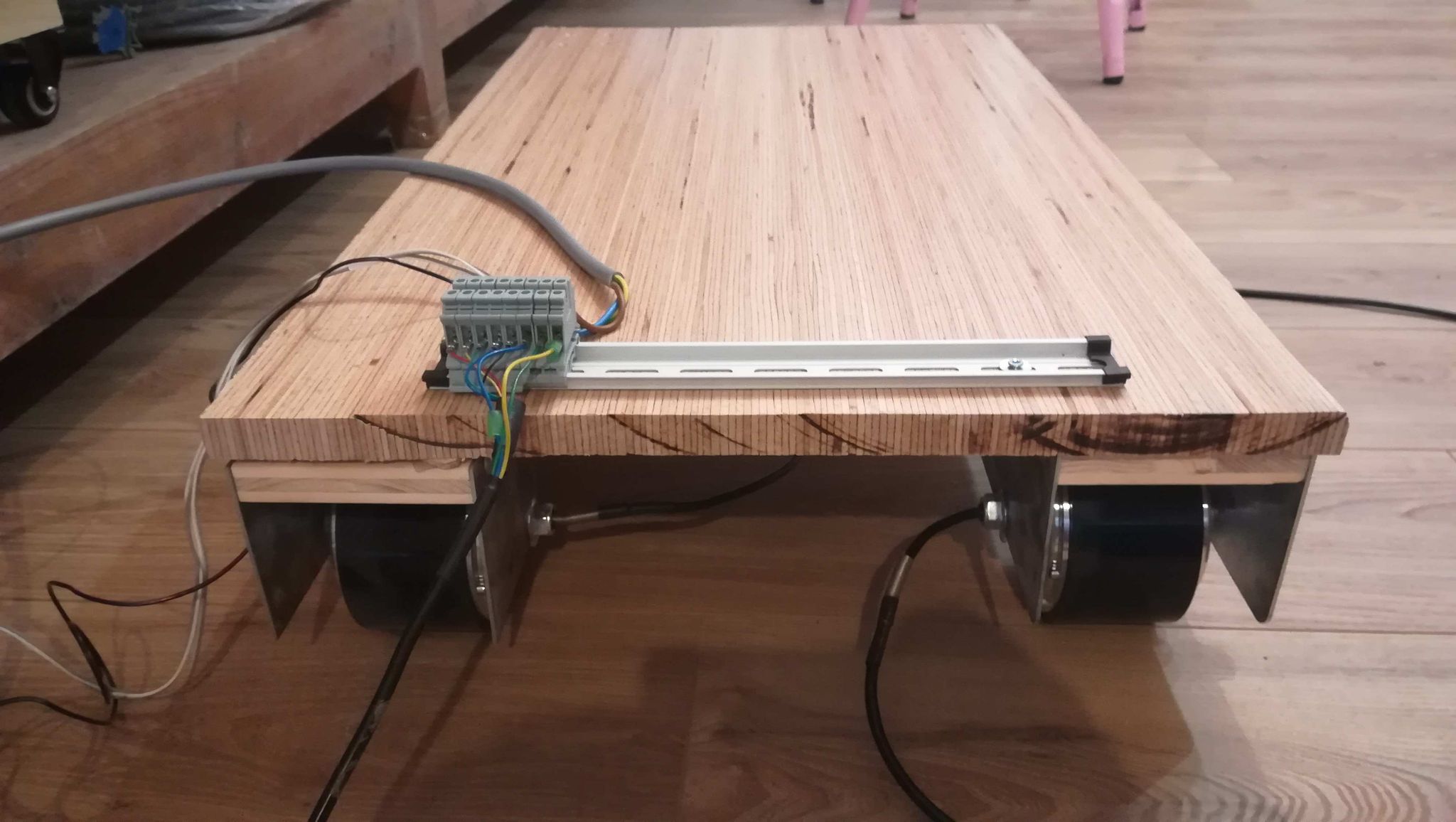
It looks as if both your raspberry pi and PSU are referenced to mains earth, so there would have been a high current path via the USB and raspberry pi, back to the negative side of the PSU.
You should either use a USB isolator, or ideally power the Pi via the ODrive - either from the ODrive’s 5V rail if it needs less than 2A, or using a DC-DC fed from the ODrive’s power input terminals.
@towen I was under the impression most grounded PSUs have DC- decoupled from the mains earth? But at least if the Pi’s PSU has a 2-pole connector (as opposed to a 3-pole connector) you should be on the safe side.
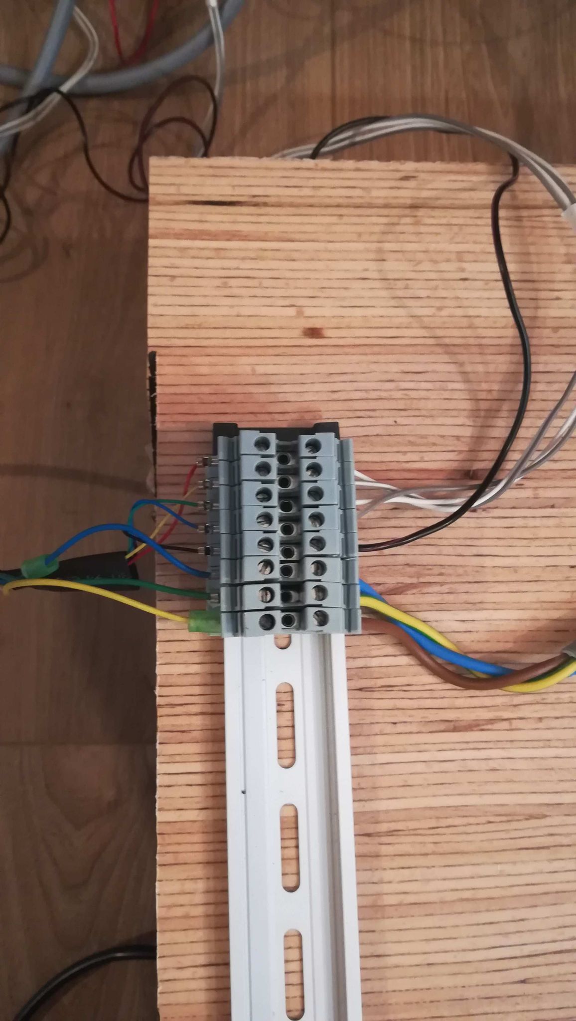
@Simon how long are your encoder cables? Long untwisted, unshielded cables would act like an antenna picking up EMI. In addition it looks like they travel through the same cable as the motor phases without shielding in between. This means they are capacitively coupled and as soon as there is switching PWM on the motor (motor calibration) the encoder cables would pick up up to 100% of these voltage ripples (depending on the length of the shared cable and the impedance of the encoder itself). Considering that the STM32’s GPIOs aren’t very robust I can imagine that this could break the STM32.
If you manage to repair the ODrive or try with another one, I would recommend to first disconnect the encoder from the ODrive (on the ODrive side) and measure the A/B wires with an oscilloscope during motor calibration.
Since your power supply says 23V…28V I would also strongly recommend to use the 56V version.
Thank you for all these informations.
Until now my encoder cables were about 3m long. I will change all the implementation and will place the ODrive as close to the motors as possible. The only “long” cables remaining will be the 24v power supply for the ODrives (which will be shielded), and the USB (or UART) cables between the RPi and the ODrives. I read on this post that the CAN was more robust than the UART for long distance communication, do you confirm ?
Unless I also place the RPi as close as possible to the Odrive as suggested, but that would make me multiply the RPis when I could use one for all my ODrives (up to 3 in the final product).
I’ll make some tests as soon as I can get some new Odrive, ans keep in touch if needed.
I can confirm that CAN is extremely robust for distances 1~10m+. UART less so, USB even less so than UART.
I’ve used CAN recently in a battery test setup with 4 CAN buses running at 500kbps each, streaming data from BMSs running at 800+ Amps in a test chamber, with 10m cable lengths. Some cables were unshielded ribbons, not even twisted. No issues at all with noise on comms.
My only worry with what you describe is the long PSU cables… You could run into ground loop issues.
I’d advise to run your PSU cables as a bus, rather than a star topology, with the DCDC that powers the raspberry pi at the end of the bus. That way, it is not in the current path between the ODrives and the PSU.