Can i modify the control logic?

i got a problem.

since i’m going to use Arduino, i changed my Odrive’s configuration.
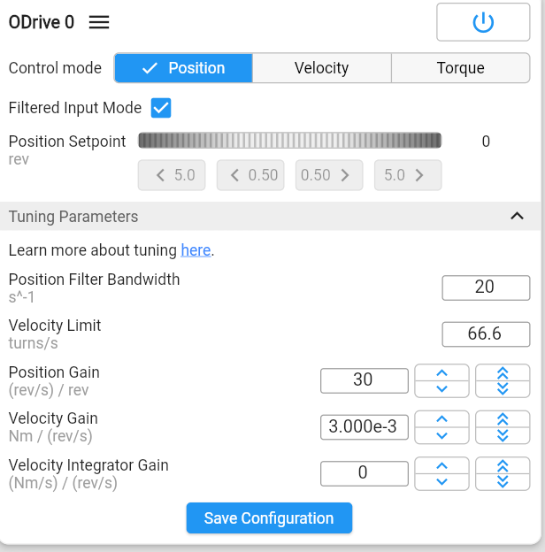
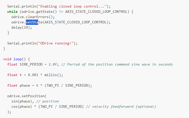
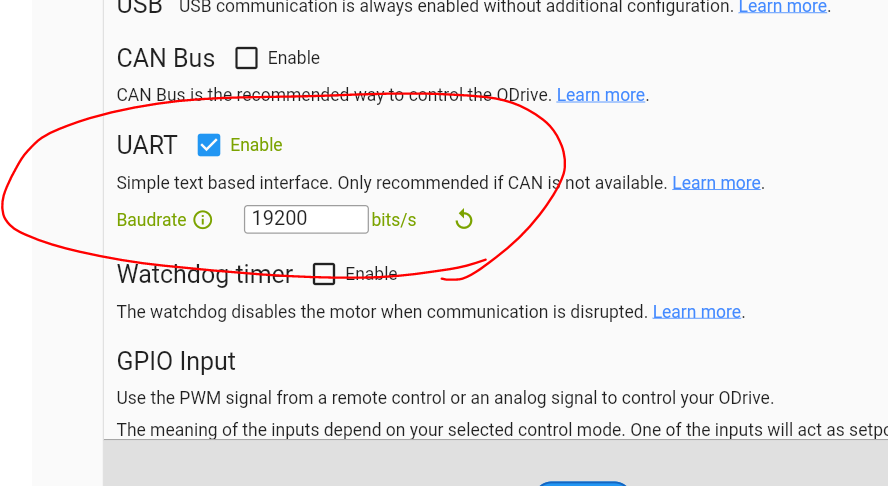
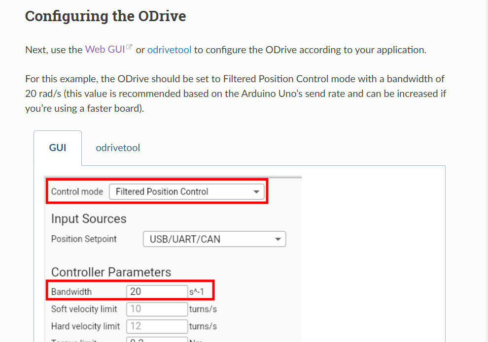
i just changed UART option enable and control mode as filtered position control like below.

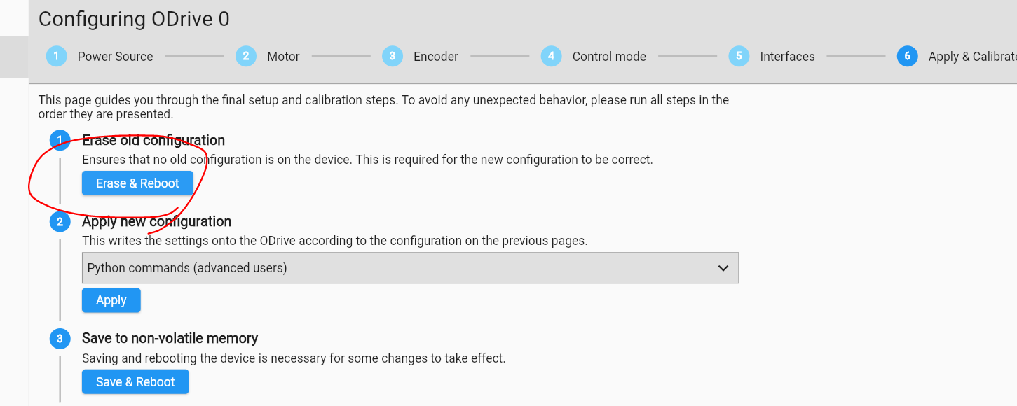
but, by changing the configuration, my previous setting like gain values was disappeared.
(because when changing settings, it requires erasing process i think.)

anyway, since i lost my previous setting, i tried to re-calibrate my motor.
but, doing so, i encountered a phenomenon which i haven’t seen previous time.

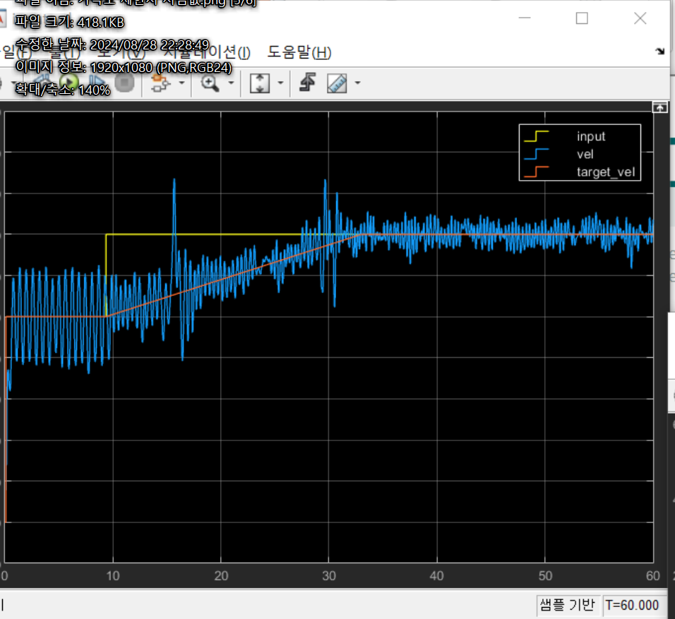
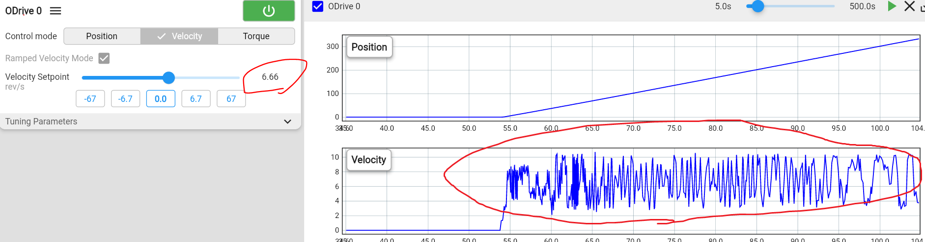
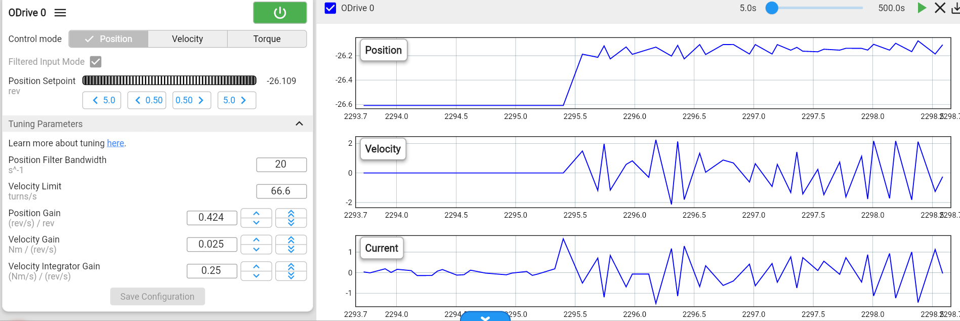
motor couldn’t go to the position setpoint.
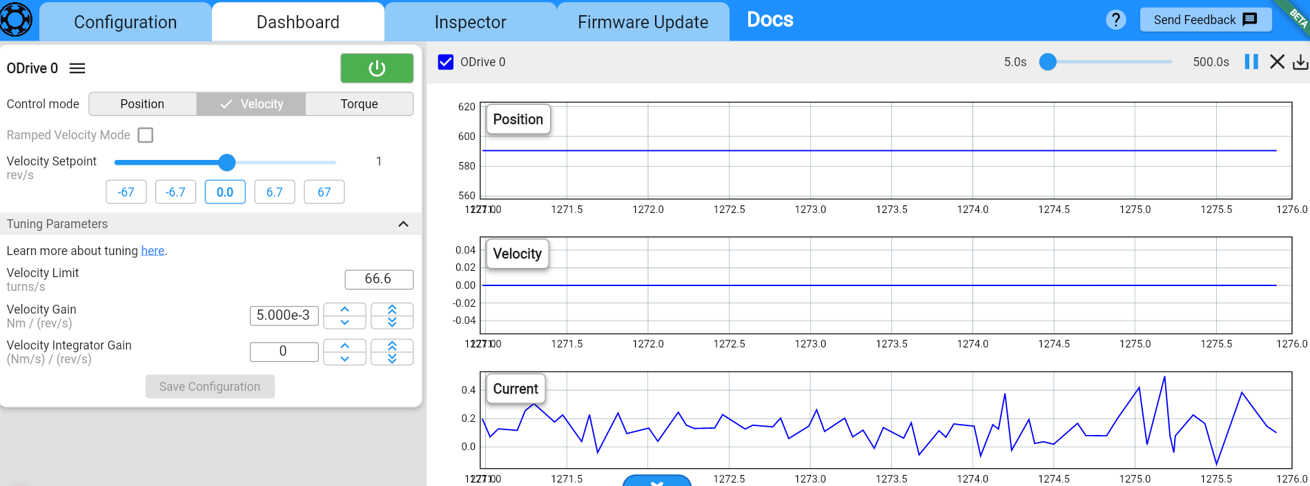
it vibrates near the setpoint like an image below.
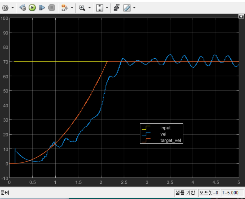
it doesn’t be seen when i use velocity control

so, i thought some causes which make problem.
please help clearing this problem.
(i also tried with intergrator factor 0)
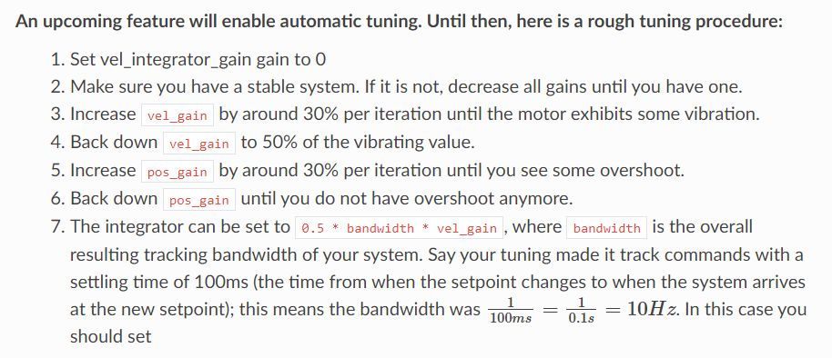
  1. position gain value
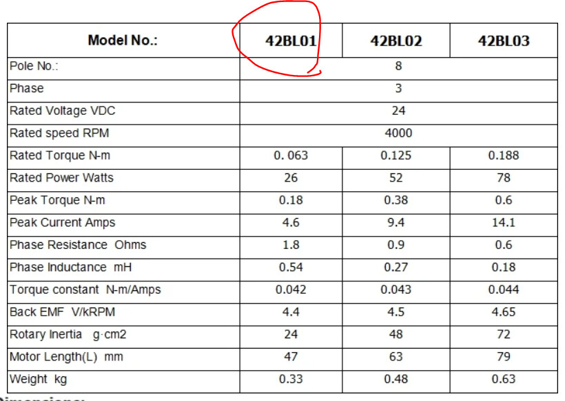
  2. hall sensor’s resolution issue
    (= the setpoint i set was the place that can’t be expressed with the hall sensor i use because it has too low resolution)
  3. control mode issue (=because of the difference between the ‘filtered position control’ and others)

and, i think the main cause is 3rd one.
→ is it possible to solve the problem if i change the control mode to velocity control?

[1]
i wrote first factor because i used position gain as 30 prevous time.
(i used gains as 30, 8.75m, 1.75m for pos gain, vel gain, integrator gain)
but i’ve been always thinking that 30 was too high, so i changed it via this time.
anyway, i increased it up to 20 to verify, but the vibrating wasn’t disappeared.
so i don’t think this is the cause.

[2]
then, i also do not think hall sensor is the problem.
because i haven’t seen the pheonomenon at previous time.
i didn’t changed my sensor.

[others]
i have other questions apart from this problem.

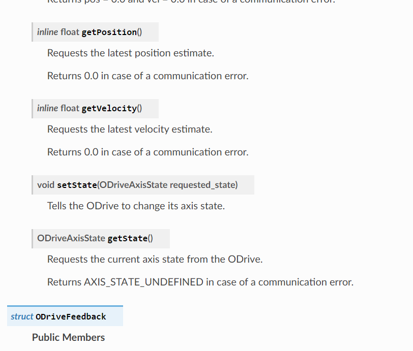
  1. can i change the control mode in Arduino? (ex. pos control mode → vel control mode)
  2. can i set the Odrive as IDLE in Arduino?
    and also can change from IDLE to any control mode? (=can i make it ‘wake-up’ when it is IDLE?)
  3. only ‘filtered position mode’ can be used when using Arduino?

Did you recalibrate the motor under no load? I think this may just be a gain tuning issue.

The pos_filter control mode won’t change things – it’s very similar to the passthrough position mode.

To answer your questions:

  1. can i change the control mode in Arduino?

yes, absolutely :slight_smile:

  • can i set the Odrive as IDLE in Arduino?
    and also can change from IDLE to any control mode? (=can i make it ‘wake-up’ when it is IDLE?)

yes, absolutely :slight_smile:

  • only ‘filtered position mode’ can be used when using Arduino?

nope, any input and control mode you want!

i’ve tried to tune the motor with light load.
now i’m trying without any load.

but, i wonder how to tune the pos gain.

the manual said that i should increase until it meets overshoot.
but, when i tired it, i feel it depends on the input.

with only a ‘+0.5 rev’ input, it is stable.
but with high ramp input like ‘+5 rev’ or clicking ‘+0.5 rev’ button quickly and steadily, the motor becomes unstable.
if i decrease the pos gain value, it seems the maximum ramp rate which the motor stays stable increases.

so i wonder the judging criteria for tuning pos gain.
based on what inputs should i determine the pos gain which can let the motor remain stable?

i’m using gains like below now.

Usually I’ll start by tuning in velocity mode:

  • I typically start by zeroing the velocity integrator gain
  • I’ll set the velocity setpoint to zero
  • I’ll slowly increase the velocity gain while perturbing the motor with my hand, until the motor starts to exhibit some slight vibration. I’ll then back off the velocity gain to about 50-75% of that value
  • Then I’ll do the same with the velocity integrator gain
  • I’ll verify these gains by giving it a velocity step response (instant increase from e.g. 0 → 1 rev/s, then back to 0 rev/s), and verify that there’s no vibration
  • Finally, I’ll change to position control mode, and do the same with the position gain – zero position gain, give it a position setpoint of zero, and perturb the motor with my hands while increasing position gain until the motor vibrates a bit, then back the value off to 50-75% of that. Then I’ll give it a few position step responses and verify good response and no vibration there.
  • It helps to turn off filtered input mode for the time being, then re-enable it when your gains are good.

i’m really sorry but the mention ‘until the motor starts to exhibit some SLIGHT vibration’ doesn’t approach to me.

** i experimented under velocity control mode **
** i set integrator gain as 0 **
** i touched the shaft (directly by hand to give perturbing to motor) under vel input is 0 **

because, when i perturb the motor, motor forces back cuz the control is alive. (closed-loop control)
so i’m confused that should it judge this reactive force as the ‘vibration’ you said, or it means the REAL (actual) vibration of the motor itself.

and, i’m also confused whether the 1 rev/s step input is right.
because the maximum velocity of my motor is 4k rpm (66.666 rev/s)
for me, it seems 1 rev/s is too low when compared to its maximum.
and, for real, the motor doesn’t work either when i input the value as 1 rev/s. (see below)

so, may i know how to proceed the tuning process under this situation?
i’ll attach my motor’s spec for your reference.
i forgot to share it to you. it’s my mistake. i’m sorry.

Thank you for your help.

i’m sorry but can you check the question i wrote above?
i’ve been waiting your reply, but i’m writing this request cuz there is no reply for some time.
i need your help.

thanks!

Hi! Sorry, thanks for the reminder.

i’m really sorry but the mention ‘until the motor starts to exhibit some SLIGHT vibration’ doesn’t approach to me.
because, when i perturb the motor, motor forces back cuz the control is alive. (closed-loop control)
so i’m confused that should it judge this reactive force as the ‘vibration’ you said, or it means the REAL (actual) vibration of the motor itself.

If you’re in e.g. velocity mode with a velocity setpoint of zero, and you reduce all gains to zero, then the motor of course won’t respond. But as you start to increase the velocity gain and disturb the shaft, the motor will eventually start to vibrate – this is what I mean by “slight vibration,” and is a sign that the gains are too high to be stable.

I then verify this with the velocity step (since the rapid velocity changes may lead to instability so I will have to further reduce gains), but you need the gains initially tuned in the first place for the velocity control to work.

May I ask what encoder you are using? Note with hall sensors due to the low resolution, position control is extremely poor, and velocity control at low speeds is quite bad.

the motor i bought has its own hall sensor internally. (i don’t use external encoder including external hall sensor)
i leave the link i bought.

then, i think i should modify the step input value because i use hall sensor and u said its performance is poor at low speed.
would it be right?

i’m thinking about 6.6 rev/s because its maximum speed is 66.66 rev/s (4000 rpm)

Sure, you can do that for tuning. Really you’re just trying to find PID values that give the motor a response that seems good – it’s okay if it’s very much just trial and error.

Thanks!

since i’m not an expert, i can’t analyze the working of motor,
but it LOOKS got stable.

i tested with velocity step input (10% of the maximum speed) and consequtive position step input (0.5 rev)
and there was no problem.

.
.
then, i want to know the Arduino command (function) which makes the mode ‘ilde’ and ‘velocity control mode’.
(from idle mode to velocity control mode, and from velocity contro mode to ilde mode)

*but, it seems there is no command to set the mode to “velocity” control mode when i searched arduino command.
i think if i set the mode as ‘closed loop control’, i can use both position control mode and velocity control mode without additional command like function ‘setVelMode()’. ← this is a virtual function that i named to explain what i’m thinking of.

.
anyway, i want to know how to change the control mode. (idle / vel control)

.

hello. i have some questions.

i extracted some measurement data from odrive, but it seems weird.
the flickering (ripple) is too much.

i extracted the data from Matlab (which is connected to Arduino and Odrive) at first
but i felt something strange.
it was that, the ripple from the reference intput was too much. (blue graph)
What’s even more surprising is that these values ​​are the ones that have been filtered.

  • a=0.1
    image

so i checked it again with Odrive GUI,
but there was no difference.

i think it’s not normal because it seems the error compared to reference input is too high under constant reference input condition.

may i have some solution about this?
and, for the last, i want to know how to change the odrive state from closed loop control to idle in Arduino environment.

.
.

.
.
Thank you always.
Thanks.

i solved it.
it was because i executed the test under no load condition,
after i gave a small load to motor, it became stable.

Thanks!

then, for the last, i want to know how to chage the control mode from ‘closed loop control’ to idle.
can you help me?

Thanks!

Great to hear it’s working out! To turn it from closed loop control to idle, you just set the axis requested state to idle. This can be done via setting axis0.requested_state in the GUI inspector (or ODrivetool, or over UART or CAN), or just pressing the green power button in the GUI dashboard.
image