Yes, it does depend on your control gains. Specifically, the position following error needs to be as low as possible in all positions, but the gains must not be high enough to cause limit-cycling (oscillation).
No limitations I’m aware of in position or current control mode… Apart from the usual “it’s a beta feature, don’t rely on it”. However, if you are still using your 4000 count incremental encoder without an index pulse, you may have problems because even if you save the calibration, it won’t be valid when you reboot, unless you use an absolute encoder or an index pulse.
pos_gain is how much velocity (in counts/sec) that the position controller will demand from the velocity controller per count of position error. vel_gain is how many amps the velocity controller will demand from the current controller per count/sec velocity error.
pos_gain x vel_gain will give you the spring constant, but vel_gain also adds some damping, preventing the motor from oscillating about its set position.
vel_integrator_gain corrects for steady-state error i.e. if it were a pure spring, there would be an offset proportional to the load. an integral term will allow you to get better accuracy under load. Make sure you have an integral term set when you do your cogging calibration.
What do you mean by “smoothest shaft behaviour” when rotated by hand? You mean low friction? Lowest friction should be achieved when you are in current mode with input_current set to 0, after having successfully activated anticogging.
Yes, this is because the anticogging is only calibrated in one direction. It’s not ideal.
For anticogging to work properly, it should be done in both directions (to cancel out the effect of friction / “stiction”) and over multiple revolutions, co-averaging all of the results to remove noise.
Maybe someone has a fork, branch or pull request for that.
so how should this calibration look like (visualy) and how long should it take?
mine takes ~5min maybe, the motor shaft moves slightly back and forth with a very slow forward component (eventually it does a full revolution).
that makes sense - sometimes it works (after reboot) sometimes it doesnt
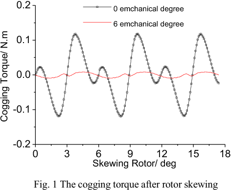
It will look like some combination of a few sinusoids. Google images for “motor cogging torque”.
For example:
This is an example of how motors with skewed slots can have very low cogging (but they also have lower efficiency, and still have other types of torque ripple)
5 mins is about normal. It shouldn’t be moving back and forth though - only forth. Sounds like you need to tighten your gains a bit.
I don’t feel competent enough but I’ll try to summarize a few things:
If your aim is to build some kind of … force feedback device (you want your motor to act as a spring):
chose a proper motor try ‘slotless’ ‘coreless’ ‘ironless’ motors
if you already have some kind of shitty motor you can try anticogging_calibrattion()
a) put the motor in a CLOSED_LOOP and than start the anticogging_calibration()
b) it takes a looooooot of time to finish this procedure (one episode of Friends should be enough) (the motor slowly moves to one direction)
c) when its done the motor quickly spins/rotates to the origin?
d) try odrv0.axis0.controller.anticogging_valid to check if the calib process has been finished
e) put the motor into possition_control mode and try
odrv0.axis0.controller.config.anticogging.anticogging_enabled=True/False to feel a difference
(it is awsome :))
f) if you have an absolute encoder or indexed encoder you can save_configuration() and you dont have to repeat anticogging_calibration (however you have to make it valid:
odrv0.axis0.controller.anticogging_valid=True)
g) depending on your gains, anticogging_calibration can be done better or worse
h) anticogging_calibration() is done in one direction (the motor rotates in one direction during this procedure), when its done there is a small difference when you rotate the shaft cw and ccw (but it is still awsome )
I think that I got the answers I needed.
Thank you guys for your help
1: You can also use motors with skewed slots or skewed magnets, or some other special mechanical shape designed to reduce cogging. But “low-cogging” motors tend to be designed for industrial use and so are out of the price range for hobbyists.
2.f) I think if you are using an absolute encoder, then it will already be valid on boot. In the same way that encoder.config.pre_calibrated=True will persist for absolute encoders, meaning that you can change state directly from boot to closed_loop without needing to do a calibration sequence.
BTW. You are already using an AS5047p. Can you just connect the MISO and SCK wires to the ODrive header, and the CS to one of the GPIOs? That lets you put it into absolute mode with 16384 counts.
Also, you could try a “gimbal motor” for this, if you can get hold of one. They are designed for open-loop positioning, which means they have very low cogging, as hobby motors go. They also have quite a lot of torque when driven closed loop from ODrive.
I’ve tried but it looks like it doesn’t work. (I get encoder failed or spi problem error - something like that)
Im trying now to get rc-v0.5.1 (maybe there are some upgrades to the spi?)
im new here and on github. I don’t know how to get rc-v0.5.1
what should be the path here to get and compile rc-v0.5.1?
Did you set the abs_spi_gpio_pin correctly?
When do you get the error? straight away or only when you try closed loop? If the latter, does the calibration all work OK?
You shouldn’t be using wetmelon’s repo anymore - use Oskar’s repo instead:
When you clone the repo, make sure you then switch (checkout) the rc-v0.5.1 branch
The procedure is the same to build the firmware and flash it
I did it for sure.
(I’ll try again as soon as I compile and flash rc-v0.5.1)
after:
I get “no module named yaml” 4 times
Ive tried pip3 install PyYAML (raspberry pi)
(thx to @Wetmelon)
this time got “no module named jsonschema”
pip3 install jsonschema
and finally no errors
after switching to rc-v0.5.1 and connecting SPI interface weird things start to happen
power supply off, odrivetool quit()
power supply on (not even connected to the odrivetool) => motor shaft is being hled by some current (nice and smooth btw )
setup:
(MOSI to MOSI, than switched to 3v3 nothing helps)
a) abs_spi_cs_gpio_pin=4
b) encoder.config.mode=257
c) cpr=2**14
d) first FULL_CALIB failed somewhere in the middle (forgot to check dump_errors most prob encoder)
e) second FULL_CALIB ERROR_MOTOR_FAILED (phase resistance out of range)
f) reboot - motor shaft released for a second and than held again, wtf?
g) erase_config(), power supply off…motor shaft released
h) same setup as above
i) full calib error: (after ~one turn of the shaft) ENCODER_FAILED, NO_RESPONSE
Hmm, puzzling… No idea why it should be holding the shaft at boot, unless it is configured to do something on startup. Are any of axis.config.startup* set?
Could be time to ask @madcowswe on this one
If you are getting phase_resistance_out_of_range try increasing motor.config.calibration_current although the defaults ought to work with the stock motor, so something strange could be going on.
You do have quite long & narrow gauge wire on the motor phases so that could be pushing the phase resistance up a bit.
Do you get anything out of encoder.shadow_count when you turn it by hand?
What are all those things you have connected to 3.3V?
clean configuration (after erase()),
ive never changed anything in the startup.
i just realized that after boot and after writing the first line:
odrv0.axis0.encoder.config.abs_spi_cs_gpio_pin=4
i can hear a little “tik” and than the motor’s shaft is held by some current (nice and smooth in both direction - looks better than after anticogging ).
than of course, calibration failed: phase_resistance_out_of_range
second try:
reboot(),
gpio=4
nothing happens (no tik heard, shaft not being held )
calibration failed after one turn
dump error = encoder failed, no response
shadow_count = 0 all the time
encoder works in AB mode, so I assume that it is not burnt.
Jumper set to 3v3, R1 and R2 resistors on AS5047p board switched as per
5v,3v3 and MOSI on the encoder side are all connected to 3v3 on the odrive side.
I’ve also put 22ohm/47ohm resistor in series with CLK as per
The phase_resistance_out_of_range is nothing to do with the encoder btw. The encoder is not used for the motor calibration, which is what’s throwing that error. It sounds as if the wire resistance puts it just on the edge of being able to pass the motor calibration at the default current. Did you try increasing calibration_current? That should fix that issue.
Your second issue is the encoder_no_response. It’s unlikely but possible that you destroyed the MISO output of the encoder if you accidentally connected it to 3.3V instead of MOSI.
I don’t suppose you have another one to try?
In my case I didn’t have to modify anything on the AMS board to make it work with 3v3 and it worked great for about 6 months (with both MOSI and MISO connected to MOSI and MISO as normal), but later on it seemed to develop some noise issues that I haven’t got to the bottom of yet. I sometimes get ERROR_ABS_SPI_COM_FAIL as I mentioned in the other thread. But before and during calibration (i.e. untiil closed_loop) it works fine.
When you switch over, I’d start by connecting MISO to MISO and MOSI to MOSI.
Also, don’t change the resistors yet. As I say, it worked fine for me.
Also, you don’t need to fit it into your 3d printed housing to test it. Just see if shadow_count is nonzero when you wave a magnet over it…
Speaking of which. That’s an unusual way to mount an encoder, tbh. Normally you want it as tightly coupled to the motor as possible - whereas you have a flexible coupling in the way. This will make it difficult to achieve stability at high gains.
In my case, I attach the magnet directly to the motor shaft with superglue. That way I take maximum advantage of the non-contact encoder (ie zero friction, zero elastic deflection).
 try ‘slotless’ ‘coreless’ ‘ironless’ motors
 )
)
 )
)
 ).
).