I understand you’re working off the jerk-constrained trajectory generation paper and I’m getting more accustomed to the code as it sits now. But purely out of curiosity, what would be the down- (and/or up-)side of generating a trajectory of positions over time based on the desired acceleration and velocity parameters and letting the positional PID do the work? It seems this would allow strong PIDs to be used for both move accuracy (as it “chases” the generated positions) and strong holding.
I think this is exactly what we do with the trajectory control mode.
I’ve spent some time cleaning up and enhancing @Wetmelon’s original implementation. If anyone is interested to test it out, it’s available here:
Please let us know if everything works, or if there are some issues.
Thanks
@madcowswe - Hmmm, I think i see it now. Y is the new position returned on each call to evalTrapTraj.
I was thrown off by the Yd and Ydd terms seemingly sending velocity and acceleration terms back. I guess I was just thinking of it more simply as a series of moves to a series of (potentially) arbitrary positions, letting the normal position-seeking logic deal with chasing down each “point”.
So what is the logic of sending the Yd and Ydd terms back and setting both vel_setpoint and current_setpoint?
Is it just an ODrive controller convention?
(And, man, does the English language fail us here - “current” as in “present time” and “current” as in “Amperage” - argh)
Yes so Yd and Ydd are the first and second derivatives of the trajectory at the present timestep. We do assist the controller from falling behind the trajectory using these; we pass the values as feed-forward to the controller. This means that the feedback (what you called PID (it’s not exactly PID, it’s close though)) only has to work to correct disturbances and unmodelled dynamics.
FYI: in this context, current_setpoint refers to electrical current (which produces torque, and hence proportional to the acceleration).
EDIT: Here is a diagram to help illustrate what we are doing:
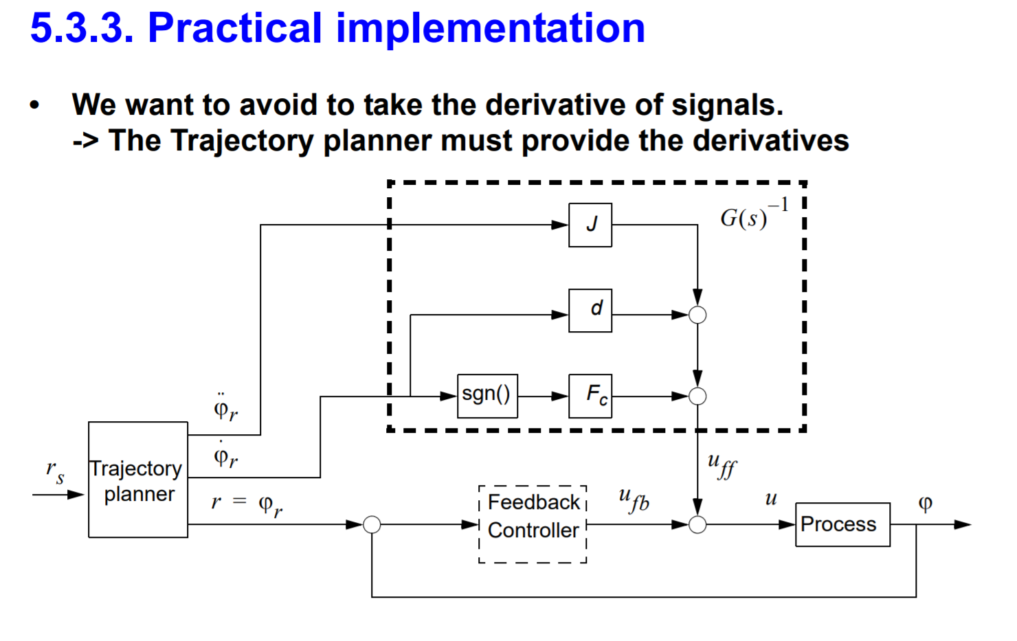
The Source seems to be an interesting read on the subject. (note our implementation is not exactly like this, but the concept of the feed forward based on the trajectory is similar).
Just so everyone is aware, the Trajectory Planner module for trapezoidal trajectories is now available in FW 4.6.
Parameters
To use it, you have a whole new module and four new configuration values:
<odrv>.<axis>.trap_traj.config.vel_limit = <Float>
<odrv>.<axis>.trap_traj.config.accel_limit = <Float>
<odrv>.<axis>.trap_traj.config.decel_limit = <Float>
<odrv>.<axis>.trap_traj.config.A_per_css = <Float>
vel_limit is the maximum planned trajectory speed. This sets your coasting speed.
accel_limit is the maximum acceleration in counts / sec^2
decel_limit is the maximum deceleration in counts / sec^2
A_per_css is a value which correlates acceleration (in counts / sec^2) and motor current. It is 0 by default, and is not strictly necessary, but can improve response of your system if correctly tuned. Keep in mind this will need to change with the load / mass of your system.
All values should be strictly positive (>= 0).
Keep in mind that you must still set your safety limits as before. I recommend you set these a little higher ( > 10%) than the planner values, to give the PID controller enough control authority.
<odrv>.<axis>.motor.config.current_lim = <Float>
<odrv>.<axis>.controller.config.vel_limit = <Float>
Functions
Use the move_to_pos function to move to an absolute position:
<odrv>.<axis>.controller.move_to_pos(<Float>)
move_incremental is not yet implemented.
ramp_to_vel is not yet implemented.
2 Likes
These commands, are they available via UART Ascii protocol? Binary protocol?
My next step would be to send the commands from the CableCam Controller.
Second question is about motor slip. The CableCam has an additional Hall-Sensor on one of the two running wheels. Hence the motor position and the cablecam position have different scaling. But more important, the motor might slip a bit when accelerating or braking. Any idea how to merge the running wheel position into the position calculation?
The commands are available on the ASCII protocol.
t <axis> <position>
I don’t currently have a good answer for you re the 2nd encoder. This is something that’s done in other industries too (high precision PnP for instance), but we don’t support it yet.
beautiful! cant wait to try it!
I finally managed to test the trajectory planning on a serious setup (rather heavy corexy design where both motors are used)
For starters , can someone explain how to tune A_per_css ? I left default value and this might partly explain what’s below
Tested on odrive 3.5 48v with FW 0.4.8
The basic concept is that I use absolute encoder positions as targets. I then scale down vel_limit / accel_limit / decel_limit of the motor that has less counts to travel so that both motors finish moving at the same time; and thus make the head move in straight line moves.
I basically issue mov_to_pos commands (one per motor). Then I regularly poll for encoder counts to check that they are close enough to the target
I am facing weird behaviors such as
- Two motors are not in sync (typically the head will not move in straight line). I have seen this in particular for some combination of moves from point B to A, but not point A to B ?!?
- Experienced error 0x40
- Sometimes, after a command was correctly execuyed by both motors, one motor would start moving alone slowly ! (As if it had received a command I did not issue !?)
- All of the sudden during the execution both motors would make scary moves (sudden high acceleration and high speed) instead of executing expected behavior
It’s a bit hard to describe without video and I cannot entirely reproduce those behavior at will.
For now I stick to using my own planner but I would rather use the built-in one 
Curious… very curious.
Please run the liveplotter while testing, with:
- Target
- Position, Velocity estimates
For one motor to start. The graphs tell us a lot about what the planner is trying to do.
I didn’t know you could use another software connection to the same odrive.
I poll for encoder estimates and motor errors every xx milliseconds. Can’t that polling and liveplotting interfere each other?
Can I have some guidance about tuning the a_per_css parameter? The manual claims that it should be tuned when mass/load is involved, which is the case here.
As a side note, I stumbled upon a cnc-made steel fly wheel that l intend to reuse to test the trajectory planner outside my corexy build
A_per_css is just inertia. Amps per count/s^2. So if you apply 1amp, how many counts / second^2 does the motor accelerate at? Or rather, the inverse.
I’m confused.
So in order to correctly configure it, I should somehow apply a 1A duty cycle, make a slowmo video to accurately measure the time it took to travel say 50cm, then assume the acceleration is somehow linear, deduct a counts/second^2, then inverse the value, and bingo: i have the right A_per_css ?
Would you have a better procedure ?
Yeah, pretty much. You don’t have to use 1A though, you can use whatever.
Or you can calculate it from the load and F = ma
Here’s a video on it https://youtu.be/wP9b-4Pl__8
A_per_css is worded that way because of how the trapezoidal planner works. It calculates the desired acceleration, velocity, and position for the whole trajectory in terms of counts. So:
Pos = counts
Vel = counts / second
Accel = counts / second^2
The position goes into pos_setpoint. The calculated velocity goes into vel_feedforward, but the acceleration must first be converted to current in Amps before it can be used for feedforward. Multiplying counts/sec^2 * A/(counts/sec^2) gives a result in Amps, which is fed into the motor control as Current_feedforward
1 Like
I am using trap_traj input mode for my setup and had a question about the motor speed. Right now I can’t seem to get the motor to move faster than it’s current movement. I’ve increased accel_lim, decel_lim, and vel_lim by huge values (just to see if it would make the motor move any little bit faster) under trap_traj configs, but it moves at the same speed. I’ve also tried increasing current_lim and still no luck. What do you guys think could be limiting it? Thanks!
Side note: I’m using 0 for my inertia value (if this makes any differnce) because I havent been able to tune it that well. With it being at 0, my motor resistance to external forces works perfectly and I have no issues with that, other than the speed being a little lower than I’d like.
controller.config.vel_limit still applies in trapezoidal planner mode. And of course your bus voltage and Kv give a theoretical max.
ok, I think I got it, thanks guys! On the same topic, my motor’s torque limit is 8 Nm, so should I change torque_lim = inf to 8? What exactly does this parameter refer to by being infinity default? And what would happen if I lowered it to 8? Thanks!
It just ends up clamping the current command. Torque = Current * torque_constant.
1 Like
That makes sense! So what exactly happens to torque when torque_lim is the default Val of inf? Or is it a must that we change it to the torque limit of my motor on its spec sheet?