I was waiting to see my odrive board functionning… and finally it seems to work. fingers crossed.
In the past, I have used some pretty classic steppers from arduino with step/dir commands to move two steppers in parallel.
In order to better use my motors, instead of linearly sending steps (basically use a fixed delayMicroseconds(us) between steps, ex: 200us ), I have designed a simple math model calculating “how much time should I wait between steps” to have a much smoother acceleration and decelleration. (prevent missed steps, go faster, and move more weight)
Typically, from what I understand, when i send to odrive
p 0 1000 0 0
The first motor will make 1000 steps in a linear fashion
I would like to get similar acceleration/deceleration functionality with odrive. But i’m puzzled about how i should implement it.
should i code it directly in the odrive fireware ? => I beleive it’s where this code would belong. but unfortuntately i am really uncomfortable with odrive source code and brushless motors principles generally speaking)
so maybe i can fall back to fast clocked arduino-like platform (ex: chipkit maybe?) and use odrive step/dir interface to send steps one by one with the right timing between steps. => it’s a bit ugly/clumsy but i think i can do it.
should i use some raspberry pi to send p commands through usb by small chunks of x steps with increasing speed until i have the right count of steps? (then race between steps per commands and usb communication speed?)
or should i sponsor someone for the code to be implemented in odrive since i seem unable to code it myself ?
I’m not sure I entirely understand what behavior you would like to achieve, but let’s make sure we’re on the same page as far as current functionality is concerned.
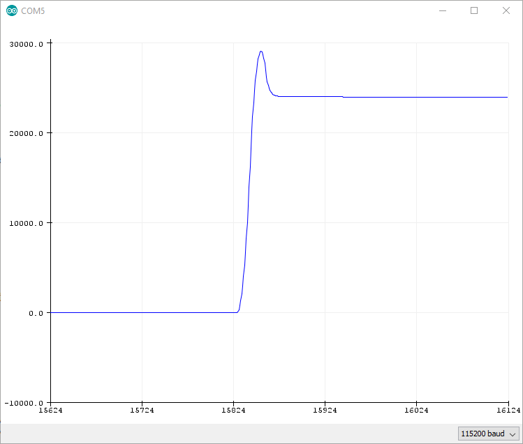
At the moment, if you send the command p 0 1000 0 0, motor 0 will use a cascading PI controller to move from its current position to the position 10000, which is represented as encoder pulses. This generally results in the highest current appearing at the beginning of the move, as the Proportional term is greatest at that point. Sometimes, this results in significant overshoot.
This is not an acceleration controlled movement. For an acceleration controlled movement, you need to change how the ODrive responds to position requests by creating a trajectory and tracking it with the position and feed forward terms (the last two 0’s in the position command). This is a planned functionality.
Right now, the best way to achieve this is probably to use a CNC controller (RAMBo, Smoothie, Yaskawa, etc) and feed ODrive the PULSE and DIRECTION pins as if it were a stepper motor driver. The # of encoder pulses per step is already configurable in the firmware.
Hi @alexisdal,
Thanks for your persistence with your ODrive, and I’m glad you are looking to take the functionality to the next level.
Let me take some time to explain how the ODrive is working right now.
This is not quite correct. When you send that command, you are simply telling the ODrive: Try to be at position 1000 NOW. This is an absolute position coordinate, so it will not make 1000 “steps” if it is already at position 1000. Also, since it tries to be there NOW, it will try as hard as it can to get there, it won’t go there linearly (constant speed). Like @Wetmelon demonstrated, the trajectory it takes depends on your tuning, but is generally more aggressive acceleration at the start and then a smooth slowdown.
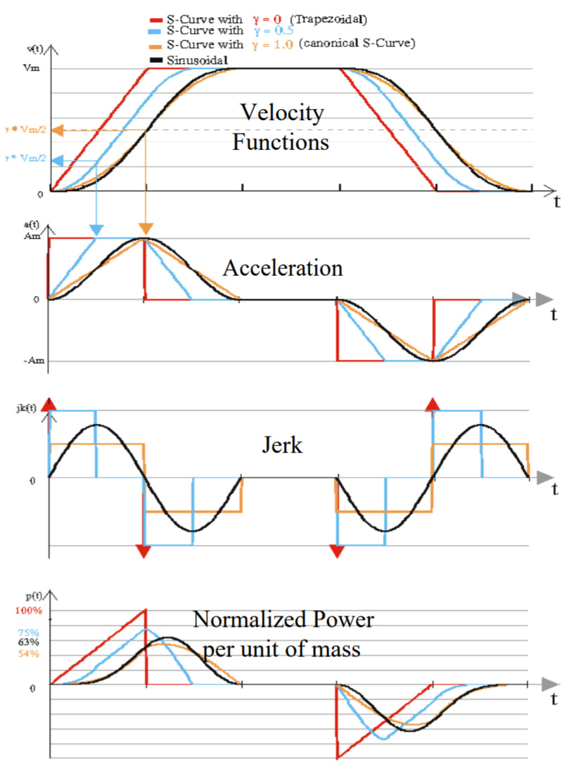
A planned motion, with acceleration/deceleration, is called a planned trajectory. We intend to make a sinusoidal velocity profile planner/tracker, see here. If you simply wish to wait for us to finish this, you can subscribe to that issue. It is not the highest on our priority right now, though if you would like to sponsor this feature, we can bump it up in priority .
If you would like to implement our planned trajectory feature, or your own, let me know and I can guide you to where it makes sense to put it in the code. Otherwise, either of your other suggestions should work:
Use an external trajectory planner on an arduino-like platform, and send step/dir signals. @Richard_Parsons has some experience with this, and should be able to give more detailed advice.
Use your PC or a raspberry pi to send p commands at a fast rate. Though it wouldn’t be with increasing speed, it can be constant speed: since the p command is absolute. To move in a linear velocity profile with motor 0, you should send something like this (in this example every 100ms):
p 0 0 0 0 (no movement)
p 0 0 1000 0 (start of move here)
p 0 100 1000 0
p 0 200 1000 0
p 0 300 1000 0
p 0 400 0 0 (end of move here)
p 0 400 0 0 (no movement)
As you can see the second parameter is the absolute position, and the third parameter is the velocity. You can ignore the 4rd parameter for now
thanks to you both. you hit the nail right on the head. I simply wasn’t aware of the vocabulary of a “trajectory” but it’s exactly what i had in mind.
Before i can sponsor or even code myself anything related to trajectories (be it in the code of odrive or otherwise), i first need to build a working prototype without it.
so it then becomes a timing issue: will i make an prototype exploiting odrive before the odrive firmware implements trajectories?
some feedback on my own attempts to implement a similar behavior/feature.
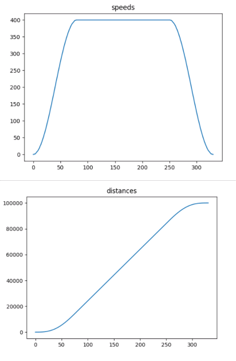
Using the suggested paper as inspiration, i came up with a cosine function to build a speed profile. Then used it to build a positionning commands to send to odrive through usb ever dt seconds (typically every 50ms or so)
(screenshot below)
but i’m facing several problems
some problems are unrelated to the trajectory planning such as:
sometimes the USB connection breaks (i’m using the builtin python odrive lib) while the boards continue to operate (motors are still holding their positions
sometimes USB continues to operate but motors no longer move
=> By repeatedly sending such commands with infinite loop, I nearly always experience either behavior within the next hour. And it can’t be related to the PC, because it’s exactly the one I have been using to stress my odrive for 24/7 during weeks a few months ago. It maybe a behavior related to physical constraint (i’ll try to detach the pulleys to make motors run freely and report)
And some problems related to the trajectory planning itself
problems to get the motors to move in sync with this approach. in my corexy design, this results in non-straight line while moving for instance
Most importantly i find trajectory planning difficult to implement from a math perspective. the trickiest part is that using a vaying speed value every dt ms in order to end up exactly at the desired position is difficult to achieve. feels like differentials equations to me
I think mostly because of this last point, I am likely to revert to one arduino shield i made two years ago to control steppers. Then use a certain number of steps per pulse on odrive to fight against my arduino being too slow to feed steps fast enough (or use a faster teensy instead, i’ll see later). It may be easier.
@alexisdal I am just getting back in town but yes I have some things to add and discuss with you. I will try to formulate a complete post tonight. I also have a few questions of things I have run into as well.
Just so you know. I thought the sine wave have the property to start with a zero acceleration, which was good because it did not stress the belts too much while starting a movement. However, it has the nasty side effect to take more time overall compared to a model where the acceleration starts above 0.
Anyway, I had some code issues. for starters while trying to sync two motors so that they terminate their movement at the same time (otherwise a typical XY command is not a straight line, which is a no go for me).
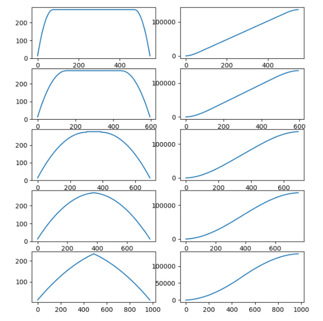
Anyway, I switch to a simple polynomial model (see bellow, speed curves on the left, positions on the right), which should give me faster startup. However, it looks like i fried my second odrive 3.2 so i can’t test it on real motors for now.
The classic way to make a straight line trajectory is to have some vector V that is the line connecting the start (S) and end points (E): V = E - S. Then generate a scalar trajectory x = traj(t), then simply scale the vector. This yielding the current position as a function of t as: X(t) = S + Vx(t)
I am pretty sure i got the trajectory right. At least with the polynomial model (it would require some more work on the sine model though). However, I have noticed that I need to send the commands very quickly for the corexy movement to be very smooth (every 0.005sec works. every 0.020sec does not).
What happens when I use a 0.020sec interval is that the belts vibrates a lot. I don’t really know how to measure it but i think at every commands, the motor accelerates, then brake to hold position, then with the next commands does the same. and again. and again. which results in the belt being pulled and released very quickly => witch makes it resonate.
My intuition is that using a PC/rpi to send position commands to overcome a missing feature of the firmware is a bit cumbersome.
How can I help to get this trajectory planning integrated in firmware?
(last time I saw the code, I was scared )
Yes, if you send commands too slow they form a rough stair-case, which indeed makes the ODrive accelerate and decelerate all the time. You can reduce the gains to help with this, or you can add an interpolator in the firmware.

 .
.


 )
)