To begin I want to thank you all. This kind of project change the way people make and think things. And I hope I will be able to give you back what you give to me…
I’m pretty new to brushless motor control. I just start making my own control few weeks ago to learn about brushless. For now I’m training on small gimbals and really small and sheep brushless driver with an arduino.
I tried to create my own control without watching other algorithme to keep my fresh eyes on this subject and possibly understand deep things about brushless.
Don’t be surprise to find strange language or idea here, I create my own technical language and theory around this subject.
Actually I have position, speed, and torque control working only with a position sensor on my gimbal motor so I choose to let me look at other algorithme to discover differences with my approche.
So I start (just start) looking at the Odrive code, and I found a lot of differences.
Current centric control
One of the main difference I found is the current centric control of the standard approach (the Odrive one). In my setup I don’t have current measurement and I don’t feel the need of measuring current for control purpose.
To evaluate the torque I compare the theoretical position of the rotor on" stepper mode" (I call it magnetic vector), and the real one given by my position sensor.
Is this “magnetic vector” thing is existing in standard brushless control approach?
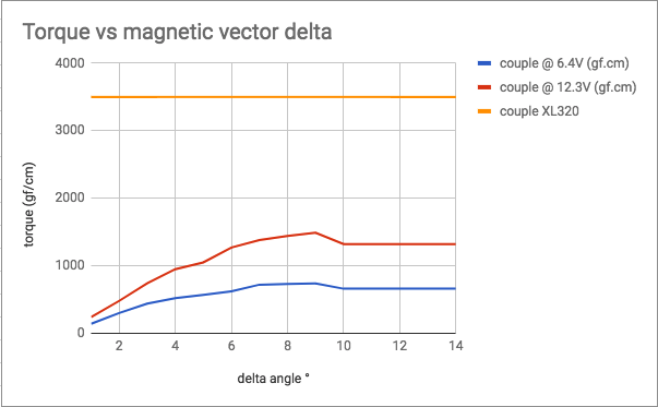
So based on my observations a “magnetic vector” shifted with a given angle (9° in my motor) at the same volatage or PWM value give me more torque.
Here is my results :
The blue and red curve give torque at a fixed tension depending on angle difference between my “magnetic vector” and the rotor vector.
The yellow one is just a dynamixel XL320 measure for reference.
Is this delta angle performance thing something you heard about?
I will have A LOT OF questions after that, I will ask them later to keep this subject understandable.
Please feel free to chalenge/ask me about my strange approach.
Why? Why not go read some resources? There are many good resources on the subject. I don’t mean to dissuade you from exploring and experimenting, but going to read the theory is respect to us, that we don’t waste our time explaining things from scratch if you haven’t spent the time to try to understand the established theory by yourself first.
Yes it’s standard. So actually what is happening is that you have a gimbal motor with large resistance, so you apply a PWM voltage vector, and over the large (~10 ohm) resistance, ohms law gives you a current (I = V/R). It’s the current which drives a torque, so you are doing open-loop current control through the motor resistance and the applied voltage. The normally used term is “current vector” and “voltage vector” (not magnet vector).
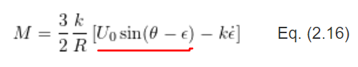
Yes the torque is proportional to Voltage * sin(delta angle):
from here.
Please go read some theory yourself first, it is basic respect for our time. We’ll be happy to help you if you get stuck, after you have tried yourself first.
P.S.
tension -> voltage
couple -> torque
If I didn’t see many french people doing this before, I’d have not understood you xP
I’m sorry I didn’t want to hurt anyone about that, this is just my learning flow allowing me to understand easily the theory. I just started reading some resources now, and one of the first I began with is this community (and your code)… thanks for answering me.
As I understand, I can use voltage vector because I have a large resistance motor. In this case inductance can be negligible and current can be directly proportional to motor resistance.
That’s probably why you have your Motor_type_t struct… Anyway I will continue digging your code and books.