edit: I think I am basically done with the code additions to support the custom hardware. Been playing with the RC for a few days and it’s been good so far, so I think I will compile this version soon and give it a shot as soon I move the encoder from the bench to the actual motor.
Note: I was able to port the code I wrote for the Due into the firmware fairly easily. 99% of it was very un-invasive. I could have kept it 100% un-invasive but I felt like this one small hard change made sense: in abs_spi_cb(): you have a uint16_t pos; which I needed to be 32 bit. Currently the value of that local uint16_t pos then goes into pos_abs_ which is declared as a uint32_t in encoder.hpp so yeah changing pos from uint16_t to 32 shouldn’t be an issue. Other than that everything else is tied to tests/switchs on that new Mode_t I defined…
So in the other word the input_pos / pos_estimate can have values higher than the CPR (just like an incremental encoder)?
edit: I am not positive yet if I will want wrapping it or not. It’s more of a failsafe oriented question. Say my encoder is 16 bit, values from 0 to 65K. And say I go to position 70K. Power loss, reboot, what does the Odrive read? 5K right?
I can’t go on with testing of this custom absolute encoder driver because the optical alignment of the encoder requires actual rotation at constant speed. I was able to align and test everything on the Due as I had mounted the encoder on a brushed gear motor I had a lying around.
However I moved everything to my custom torque motor in order to test the modified ODrive firmware, but I can’t get the sensorless mode to work correctly. Been at it since yesterday, went through the few Discourse threads on the topic.
My prototype motor type is 2, my KV 3.18 (yeah it’s really low and wondering if it could be the issue), 8 pole pairs.
Calculated the flux linkage to ~ 0.210, and the velocity set point to ~ 125.
I tried playing with these numbers, order of magnitude up and down, just to see and I get the exact same behavior, no change at all.
the first weird thing is: with all the settings set, going into requested_state 4 (motor calibration), nothing happens. Maybe that’s normal. not sure. But no visible movement.
the second weird thing, going into sensorless gets the motor started, maybe 1/4 of a turn or so, then start oscillating around a position, eventually stops but basically holding position (current goes up on the shunt), I have to idle it to get out of sensorless. No error whatsoever.
then if I hit sensorless again, it will repeat: another 1/4 turn or so, then oscillates, and hold position at max current/torque.
Playing with vel_setpoint, vel_gain, vel_intgain, flux linkage have no impact on the behavior described above whatsoever.
I thought the issue was with the calibration. But going fresh in the board, iscalibrated is false at boot up, hitting motor calibration (state 4) does not “move” anything but does raise iscalibrated to true (guess it’s doing what it’s supposed to?).
I did try the offset calibration, and it goes through a full turn or so, but doesn’t go back (not sure if it’s supposed to, I’ve only been playing with full calibration up until now) - and it throws an encoder error as it should. I have a year or so worth of testing/tuning with this motor mounted with an incremental encoders, so I know it can calibrate fine and as such sensorless should also work. It is my understanding during full calibration the motor is spinning forth and back in a somewhat sensorless manner right?
If you have any idea of what might be going on please let me know. By the way what is the normal behavior expected from the “AXIS_STATE_MOTOR_CALIBRATION” (state id 4)
The next gen motor prototypes will come in soon, but it will be a while before the rotation stage is setup. It will allow me to spin the motor relative to the encoder for alignment purposes, but in the meantime I was hoping sensorless would be able to do that.
edit: @madcowswe r Re: possible change to variable type in the RC
Here’s the variable I was referring to. It is specifc to Encoder::abs_spi_cb()
it’s being assigned the value coming from the buffer, which itself is a uint16_t as well, declared here:
eventually that the value of that ‘pos’ variable is copied into ‘pos_abs_’ which is declared here (as a uint32_t):
The change I would suggest is:
in, encoder.cpp Encoder::abs_spi_cb(), replace:
uint16_t pos;
by
unint32_t pos;
that function is what I (or anybody else adding support for SPI abs encoders) will use anyway to read the data from the buffer. In my case I am reading 5 8bit words from the register and converting that into a 24 bit value which I store in a uint32_t (I am personally the suggested change above). I haven’t checked everything yet but it looks like everything down from this point is 32 bit.
Looks like the sensorless isn’t made for type 2 motors, we tried another one today (with an even higher resistance) and it would trigger errors where the bigger gimbal motor would not.
Luckily I found a way to make the new absolute encoder fit mechanically with an AMT102-V, so tomorrow we should be able to fine tune the custom encoder alignment after which we can start testing of the modified firmware.
Currently the RC0.5 has initial Absolute support for two different SPI encoders.
@Wetmelon
I have a follow up question on the RC change on pos_setpoint being read only and input_pos as direct replacement.
This change suggests that pos_setpoint as target of the PID “can” be different than input_pos. Is this the case in position control? If so under what conditions/scenarios would the target of the PID loop (pos_setpoint) be any different than input_pos in position control?
I’ve developed a tracking mode that is using position control. That tracking mode is a high level control loop that is external to ODrive and managed by an external controller communicating with the ODrive through UART/ASCII. One of the thing that this external loop is doing was measuring the error between the old “set_point” and “pos_estimate” which is the “real time” position readout. This proved to work pretty well. I’d like to make sure I understand how input_pos differs from the pos_setpoint. At first glance, for my specific purpose I feel like the error I am trying to assess should now be calculated off input_pos and pos_estimate. But I could be wrong and if it makes more sense to look at pos_setpoint I’ll do that.
Quick update: the ODrive is now flashed with the modified firmware (modified from the RC0.5) but I’ve yet to enable the absolute stuff yet as I need to make sure the GUI/control software is working correctly with the changes made to pos_estimate.
Cheers!
edit: I noticed the input mode were not explicitly declared to a value like errors, control modes, or axis states. I was able to change states through ASCII by just sending a number as parameter so I guess it’s not required.
Update!: I think I got the input_mode changes down. I have a weird problem as the input_mode doesn’t default to 1 but 0. Saving configuration and rebooting doesn’t help and every time I have to set it to 1 (passthrough) to enable position or velocity control to take the input pos/vel.
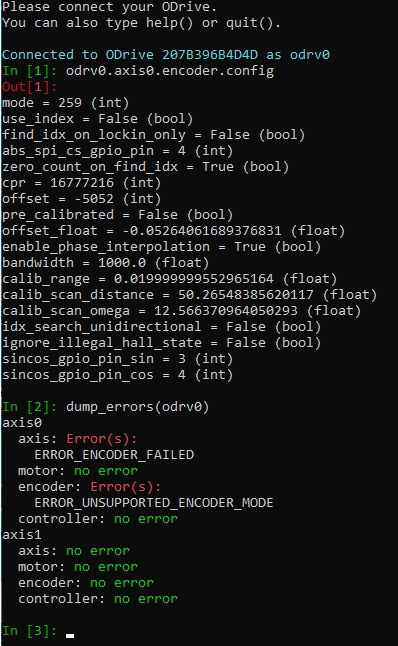
I did my first power on with the custom encoder installed.
Odrive is throwing a 0x08 error (unsupported encoder).
that also is very weird:
I have set a custom mode 0x103 (259 decimal).
in the encoder.cpp the only 3 pieces of code potentially throwing a 0x08 error are switches.
I have a case defined in all 3, so the only explanation is that somehow the switch is ignoring the additional case I defined.
it might be easier to understand what I mean if I copy pieces of my code:
inside encoder.hpp I have this:
 enum Mode_t {
MODE_INCREMENTAL,
MODE_HALL,
MODE_SINCOS,
MODE_SPI_ABS_CUI = 0x100,   //!< compatible with CUI AMT23xx
MODE_SPI_ABS_AMS = 0x101,   //!< compatible with AMS AS5047P, AS5048A/AS5048B (no daisy chain support)
MODE_SPI_ABS_AEAT = 0x102,  //!< not yet implemented
MODE_SPI_ABS_ZSI = 0x103,   //!< compatible with ZSI's custom hardware
};
then here are the 3 switches that throw a 0x08 error:
void Encoder::sample_now() {
switch (mode_) {
case MODE_INCREMENTAL: {
tim_cnt_sample_ = (int16_t)hw_config_.timer->Instance->CNT;
} break;
case MODE_HALL: {
// do nothing: samples already captured in general GPIO capture
} break;
case MODE_SINCOS: {
../..} break;
case MODE_SPI_ABS_AMS:
case MODE_SPI_ABS_CUI:
case MODE_SPI_ABS_ZSI:
case MODE_SPI_ABS_AEAT:
../..
default: {
set_error(ERROR_UNSUPPORTED_ENCODER_MODE);
} break;
}
}
next one (not copying it) is in Encoder::abs_spi_cb()
and last in Encoder::update()
the weirdest of this problem is that the error will only get thrown if it can’t find a matching “case” for the defined encoder mode
edit: I recompiled and reflashed and it seems like the flashing process doesn’t erase the memory. Is this normal? Which would explain why the defined 0x103 is not being picked up by the switches
edit2: I did an erase config after flashing, that didn’t resolve the problem
edit3: wetmelon suggested on discord possibly missing a break; before the Switches “default” statement, which would push into default. I double checked and all 3 switches have break’s before the default. I couldn’t find any other piece of code that pushes a 0x8 encoder error anywhere. Which leaves me with original theory that my declaration for the custom mode isn’t being registered somehow, and so when I set the mode to 0x103 it systematically defaults out in the 3 switches causing that 0x8 encoder error. I want to believe that it is linked to input_mode issue, which is somewhat similar in that they both rely on enum declaration in encoder.hpp and controller.hpp respectively. I’ll try to flash directly from VScode using an STlink, perhaps there is an issue with dfuse
ok I am now sure the 2 issues (input_mode stuff) and my 0x08 error on the customer encoders are not linked!
Here’s what I found on the input_mode issue.
First of all, as a sanity check I decided to check I was getting the error in python command line since all I do is through Ascii. Just in case.
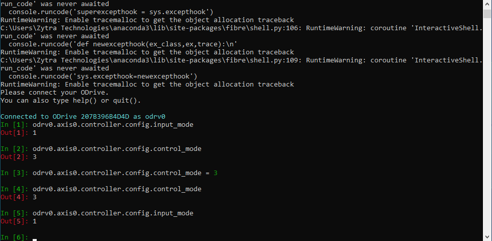
Sure enough, I could not replicated the issue with Python. After a clean flash, erase, going straight into python cli does return 1 on input_mode.
Next, going straight into ASCII command line without running any preliminary (scripting/config) commands, it also returns 1 on input_mode.
So I started to slowly un-commenting stuff to see which command create a problem:
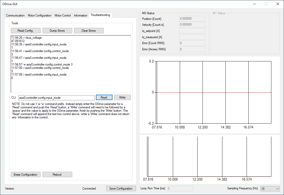
I found that setting control_mode a value (3 in my case, which is also the default, other values game me the same results) systematically also sets input_mode to 0.
I went back into python, and repeated the same command: odrv0.axis0.controller.config.control_mode = 3 then calling odrv0.axis0.controller.config.input_mode, which returns 1 as it should.
Repeated the process in ASCII CLI and input_mode always returns 0 after setting control_mode to any value.
I did a test with putty, not super practical UI but I was able to verify the issue - so at least I know for sure my GUI is not the cause
edit 3:
I remembered one of the RC change is the fact ASCII ‘w’ commands now executes hooks. Perhaps the fact control_mode affects input_mode when using ASCII has to do with a hook that shouldn’t take place. So I tracked the ASCII commands as far as I could and found this:
I can’t really tell if there is a hook defined for axis0.controller.config.control_mode but I don’t think so. Or maybe I just can’t recognize what the hook is supposed to look like. If there was one I’d think it would show here:
it’s only happening with ascii over usbser driver (haven’t checked the onboard uart yet, might do that tomorrow). I repeated the issue with putty and my own gui. every time control_mode is written to, input_mode is set to 0.
I looked for a write hook, even commented out what I think was the hook and it gave me the same behavior. So if a hook is the cause commenting out lines 829-831 in fiber’s protocol.hpp did not fix it.
custom encoder code
I tried a bunch of different things, not being able to send ascii commands while debugging isn’t helping. I added additional error setting for the encoder to identify which of the 3 switches was causing the trouble. turns out, the first and third are outputting the error. And I suspect the third would also but I never get there.
I changed the order in the case statements, no change. I tried using a hard coded 259 (instead of the enum label). Same result.
At this point I think that the axis0.encoder.config.mode is never applied to the mode_ variable inside encoder.cpp. Which is weird cause it is! every reboot when Encoder::setup() is executed:
mode_ = config_.mode;
Is there another place that the enum labels would be used for some entry verification of some sort?
setting encoder.config.mode to 257 (AMS) makes the errorr 0x8 go away.
Edit: I made a tiny of progress. The 0x08 (unsupported encoder) error is getting triggered somehow when these lines (365-370) are executed.
I am able to completely remove the error by removing this test and just executing the line that’s part of the RC (that line is not sufficient as I need to use a larger buffer).
keeping my code but changing the size from 5 to 1 also removes the error 0x08.
I do have the datasize set to 8 bit instead of 16, and I am using a different buffer variable array:
what’s puzzling me is this 0x08 error which is triggered in a different part of the code and the only explanation for it is that mode_ is being assigned a value that makes the case statement false and get me through the default case which triggers that error.
Edit: Still don’t have an explanation as to what is changing the value of mode_
But having isolated the error to be triggered when executing the hal spi transmit received DMA I played with the size of the data to send, brought it down to 1 (same as for the AMS/CUI stuff) and it wen through not rejecting a 0x08 but instead the more likely 0x80 corresponding to a fail SPI comm which is what I want at this point since I expect some tweaking of the SPI parameters (baudrate, edge/phase, etc). I increased the value up to 4 without throwing that 0x08, and it’s only when the size of 5 is used that it starts throwing the 0x08. Chasing my tail a little…
…but this brought me to dig in that direction and found that I did majorly overlooked the HAL SPI tx/rx complete callback that’s located inside low_level.cpp
I added another test on mode_ so that the tests would take place off the correct buffer (using my larger one).
Hopeful, I compiled and sadly it’s still throwing the same error. I might pull the logic analyzer to see what’s going on those SPI pins. I am expecting that with that 0x08 I’ll probably won’t see anything but who knows.
Is it possible that I am transmitting/receiving too much data and that somehow the loop is already trying to transmit/receive before the previous message was received. Trying to make sense of why would the size of the TX message would result in different error output.
I need to send 5x 8bit bytes, the message defined in the buffer declaration is: A6,0,0,0,0.
The 4 bytes at 0x00 are meant to keep the communication open while the encoder is transmitting, but really the 0’s are ignored.
That being said, something is preventing me from setting that buffer to 5. One of tests I did yesterday was to basically comment all my code, and gradually observing what error code was being thrown out. That’s how I realized the issue was coming from that line. From there I decided to change the buffer size to 1. The 0x08 went away immediately. But at this point I was finally seeing something happening on the SPI bus.
I gradually increased the buffer size and I still see stuff happening on the SPI bus with the buffer size to 4.
At this point I decided to focus on cleaning up my settings to see if I could get the encoder to talk/respond.
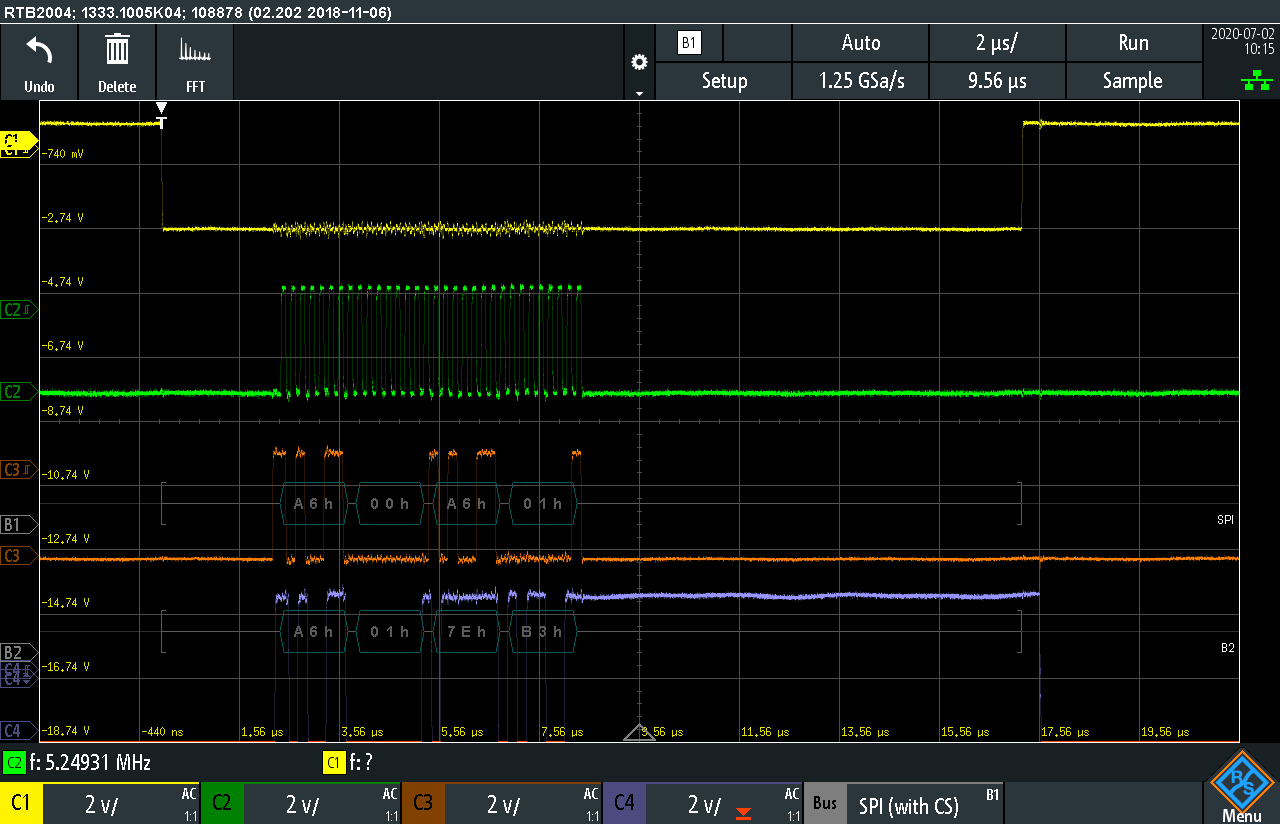
CS on channel 1, CLK on channel 2, MOSI on channel 3, MISO on channel 4.
B1 is the decoding of MOSI
B2 is the decoding of MISO
Note: my prescaler is 8 so the clock speed is 4 times faster than with the AMS/CUI (I did that thinking perhaps the reason why I could not set the buffer to 5 was that the bigger buffer was taking too much time to get processed)
MOSI shows the first 2 bytes are proper (0xA6, 0x00)
However starting on the 3rd byte, MOSI is incrrorect. A6 should not be there (even though it is ignored since the encoder is in the middle of pushing position data)
On MISO everything is as expected (first byte A6 is normal and means the encoder has received the position read command, and the following 3 bytes are position data; because I am missing the fifth byte the CRC data is missing)
The real good news are:
that physically moving the rotor does change the numbers on MISO
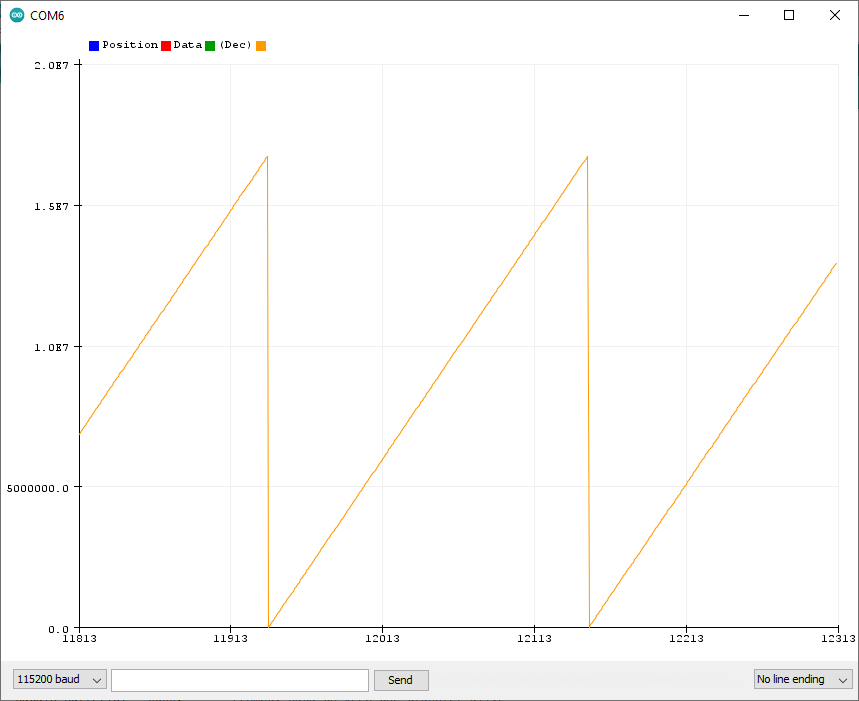
running pos_estimate on a loop does show values and the position does plot properly on the graph
One weird thing that is happening is when turning the rotor (moving the encoder position) there is a zone (very repeatable) where MOSI shifts down almost as if its polarity or phase had changed. MISO on the other hand is not affected whatsoever and the ODrive is able to read the position i.e. looking at the pos_estimate on a graph shows normal behavior. Really weird.
comments/questions:
Although it’s great I just can’t make any sense of why I can actually read the data.
Because, in my code, unless CRC has been verified as valid, the reconstructed position data from the 3 middle bytes are never being applied to the ‘pos’ variable. But perhaps because the fifth byte is not read, it must be 0, so the CRC verification code is happening, I am just not sure how the CRC is actually found valid. I won’t worry too much about that, as I know the CRC decode is working since it’s been tested extensively on the Due prior to starting these tests on the ODrive. For now the real questions are:
why am I not able to set the buffer size to 5?
why is MOSI not reading 0xA6 followed by strictly 0’s (the Tx buffer must be overwritten by the Rx buffer somewhere - I should be able to find where if it’s simple rx/tx variable error?
why is the setting of CS back to high taking so much time after data has been captured by the callback? Timeout?
here’s how my Spi init is defined (all the other settings not listed are the same as the default for AMS/CUI)
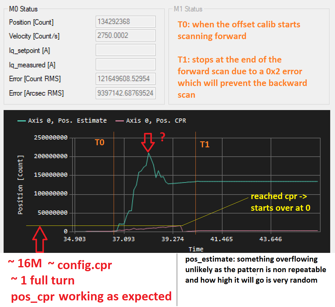
Update: still digging but I think it’s possible there is an issue with pos_estimate.
I initially thought I was having noise issues because the “jumps” in pos_estimate would be systematic while trying to calibrate (on the forward scan, it errors out before the backward scan), and a lot more difficult to trigger this problem when moving the rotor by hand.
I since then added pos_cpr to my plots and the pos_cpr is basically as expected - not perfect, some slight oscillations which could be cogging (test motor, high resistance but very coggy as 12N14P…).
I also thought about overflowing but after repeating the test several times, how high (or low) it will go seems random. I also looked through the offset_calibration function and at first glance it doesn’t look like any of the variable used for the calculations/estimations could be overflowing, but I’ll need to take a closer look.
Not yet but I am considering at least providing the executable.
It was meant to be more of the UI for the project I am working on but it slowly migrated into more of a development platform for this project. So it is slowly being populated with pretty much all ODrives parameters. It has a bunch of ODrive-external features most of which are either done or close to being done, like autotuning, a position tracking mode.
Huh, fair enough!
Btw the one thing that really makes me dislike .NET apps (apart from Microsoft) is that they don’t work in WINE…
As for your encoder issue… Have you tried looking at shadow_count? or count_in_cpr? (if these are available via the ASCII interface) - these represent the position as read directly out of the encoder (shadow_count is unwrapped whereas cpr wraps around), whereas pos_estimate comes from some kind of state observer or Kalman filter afaik.