Adding support for another SPI absolute encoder

Hi guys,

I’ve been keeping an eye on absolute encoder development/support and it seems like all SPI encoders are using a slightly different version of the protocol.

I am looking at eventually upgrading my system’s encoders to absolute, and it seems like the SPI Slave protocol of the encoders I will be using is really close to that of the AS5047P. The resolution is a bit different (22 bit initially, and will be pushed to 24 or 26 down the road through an interpolator, it’s a high resolution application currently working with an odrive and 14M+ count incremental encoders) so there is no doubt I will need to write a driver for it.

I was wondering where would be a good place to start looking at the driver written for the AS5047P for instance?

here’s what my encoder SPI timing is looking like:

and here is the SPI timing for the AS5047P:

cheers

See this function https://github.com/madcowswe/ODrive/blob/devel/Firmware/MotorControl/encoder.cpp#L377-L414 and https://github.com/madcowswe/ODrive/blob/devel/Firmware/MotorControl/encoder.cpp#L325-L347

you’ll need to add new case statements to configure the SPI peripheral as desired, then calculate the position based on that configuration.

1 Like

Thank you!

I knew both of these segments would be updated but for some reasons I was looking for bits of code related to timing. I noticed the (slight) differences in the minimum HIGH/LOW duration and figured these would need to addressed so that’s where I was starting. Your response suggests that I don’t need to worry about that. Are these differences insignificant enough? or is there some sort of signal adaptation taking place at the F4 level through its SPI driver?

Cheers

The timings are for hardware designers, you don’t have to worry about it. You just have to care about phase, polarity, and clock speed.

Thank you @Wetmelon for the quick and helpful replies!

Hey, I got a couple of questions:

  1. So it seems SS and SCK on my encoder follow the same standard as the AMS. However it seems that the MISO/MOSI signals are inverted on my encoder compared to the AMS (MOSI is leading on the AMS, MISO leading on mine). Is this a problem? Per the devel encoder markdown the MOSI pin is not even available on the CUI encoder.

  2. I haven’t started trying to figure out polarity/phase/baudrate yet

  3. resolution: the encoder actually outputs 4 bytes for the multi turn position and 4 bytes for the single turn position.

Does this line control the length of the message (position) sent by the encoder?

Cheers

Hey, here’s a quick update.

So, it looks like my encoder is using a specific command to request a read that differs from the way AMS is doing it (sending a 0 or 1 on bit #14).

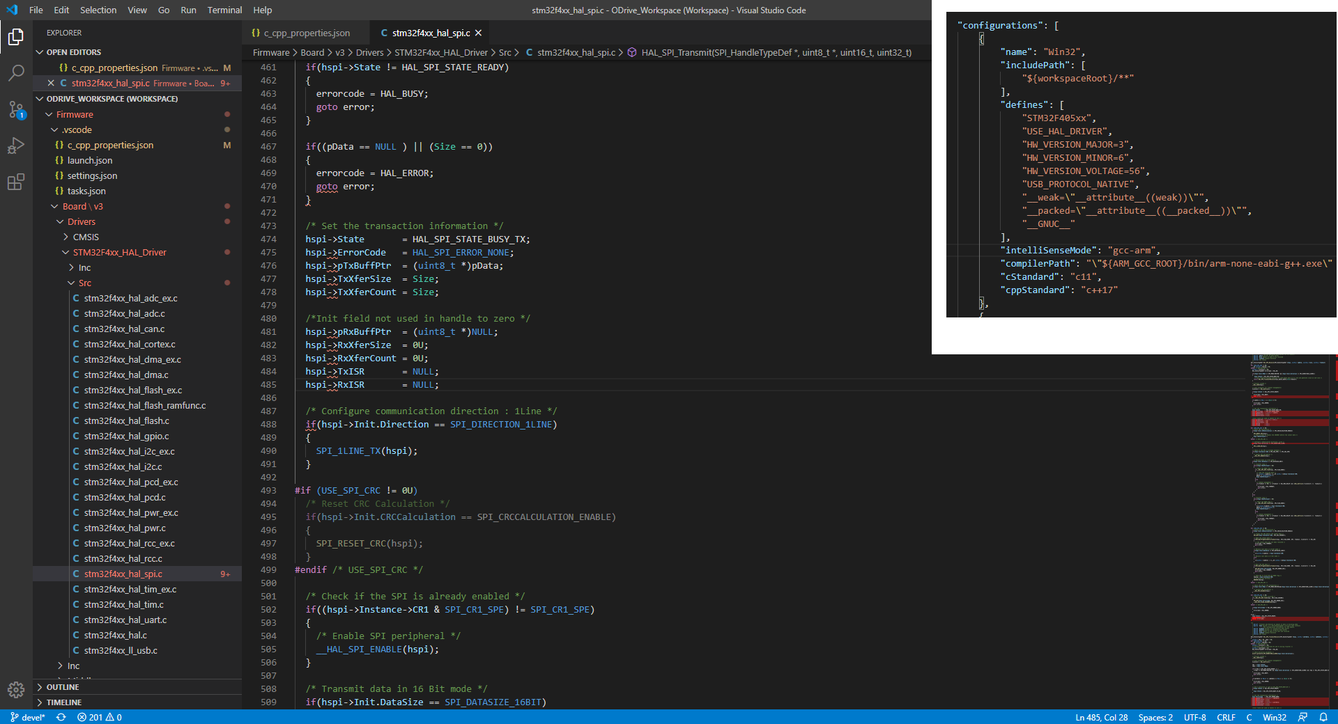
The command (send/receive) in the encoder.cpp is defined in the driver itself (stm32f4xx_hal_spi.c)

the function Encoder::abs_spi_start_transaction() in encoder.cpp has:

    HAL_GPIO_WritePin(abs_spi_cs_port_, abs_spi_cs_pin_, GPIO_PIN_RESET);
    HAL_SPI_TransmitReceive_DMA(hw_config_.spi, (uint8_t*)abs_spi_dma_tx_, (uint8_t*)abs_spi_dma_rx_, 1);

Right now I am trying to understand what is sent to the encoder to trigger a read. Here’s what I think:
hw_config_.spi contains config information on the SPI parameters, which I think may need to be changed for my encoder, not sure yet
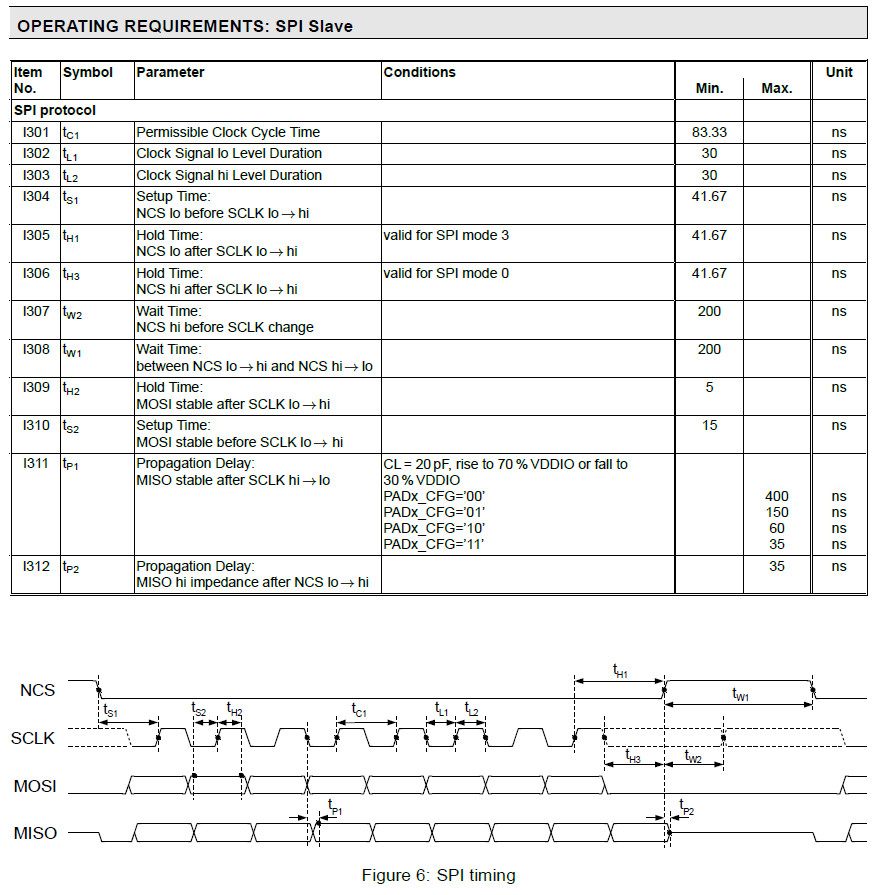
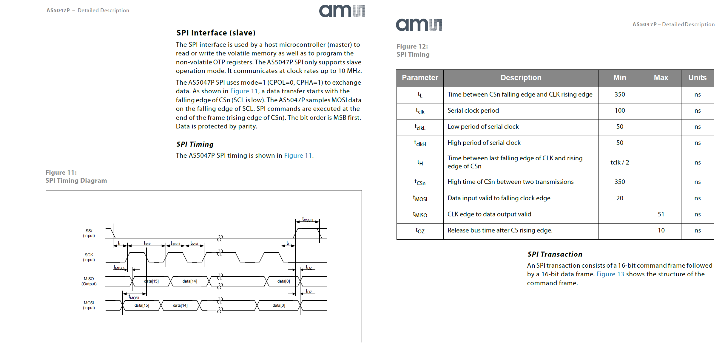
(uint8_t*)abs_spi_dma_tx_ this one is really what I need to change. Right now it is defined in encoder.hpp as uint16_t abs_spi_dma_tx_[1] = {0xFFFF}; which was confusing me a little bit at first. But as it turns out per the AMS datasheet the command frame is a 16bit word where bit 15 is parity, 14 R/W (1 for read), and 13:0 as the address, in which case you are reading at the address 11 1111 1111 1111 (or 0x3FFF), so all together 0xFFFF makes total sense.

Next step, I will use a DUE to send my commands and see what the encoder is returning on the oscilloscope.

Aside from this “command” question, my encoder is also doing verification differently by sending a CRC. So it seems that there is no polarity to deal with. A bit odd.

Lastly, the position data is sent through 4x 8 bytes for MT followed by 4x 8 bytes for ST position. I have no need for MT information and will assume the ODrive doesn’t use MT anyway. So I’ll have to ignore those MT bytes and only focus on the ST bytes. I am hoping the F4 chip can read this amount of data without significant slowdown.

Also, random side question: does anyone know intellisense does not work for the board drivers files? It compiles fine, just unsure why it’s underlining all files with many errors. All of the firmware files are fine, it seems only the .c and .h inside the board/drivers folders are effected.

Cheers

1 Like

This is actually related to point 1. I’d have to look it up again, but one of them says to sample on a rising or falling clock edge, and the other is… I forget lol.

It should work. You may have to set ARM_GCC_ROOT in your PATH and change your configuration (see bottom right corner) depending on what platform you’re using. Worst case, you can modify c_cpp_properties.json
image

Thanks WM

yeah that intellisense issue is a bit weird, I’ve got everything you mentioned. not a big deal though.
here’s what I have for reference:

Hey guys,

So in the encoders markdown for the devel build it says:

  1. Connect the encoder to the ODrive's SPI interface:
  - The encoder's SCK, MISO (aka "DATA" on CUI encoders), GND and 3.3V should connect to the ODrive pins with the same label.
  - The encoder's MOSI should be tied to 3.3V (AMS encoders only. CUI encoders don't have this pin.)
  - The encoder's Chip Select (aka nCS/CSn) can be connected to any of the ODrive's GPIOs (caution: GPIOs 1 and 2 are usually used by UART).

MOSI to 3.3V. I guess the reason you have this here is because it turns out the AMS encoder will send a position read comment upon receiving a logical high? Because the AMS doc calls for a 0xFFFF command to trigger a position read.
In my case, I’m not that lucky and the position read command is different (and only 1 byte long). I will need to MOSI wire for sure.

The Odrive has a MOSI pin. Not really a question but please correct me if I’m misunderstanding:
In the firmware we have:

        uint16_t abs_spi_dma_tx_[1] = {0xFFFF}

(defined in encoder.hpp), and then we have this (in encoder.cpp):

        HAL_SPI_TransmitReceive_DMA(hw_config_.spi, (uint8_t*)abs_spi_dma_tx_, (uint8_t*)abs_spi_dma_rx_, 1);

So when the Odrive executes this transmit/receive command, if I was to look at the levels of the (unwired) MOSI pin with an oscilloscope/decoder I would see 0xFF, right? If so, why not just hooking up AMS’s MISO to ODrive’s MISO then? Bonus question: why only send 1 byte when the buffer was defined by 2?

Cheers

You can hook up MOSI to MOSI and MISO to MISO, or you can skip the extra wire that might have noise and tie it straight to +3.3V so it reads high each time you clock. In your case you’ll need to send the specific code, so hook up MOSI to MOSI

Let’s look at the interface of HAL_SPI_TransmitReceive_DMA:

HAL_StatusTypeDef HAL_SPI_TransmitReceive_DMA(SPI_HandleTypeDef *hspi, uint8_t *pTxData, uint8_t *pRxData, uint16_t Size);

In other words, we need to pass:

  • A pointer to the SPI struct that contains the configuration we care about
  • A pointer to a block of memory that contains the data we want to send (typically an array)
  • A pointer to a block of memory that will be filled with the received data (typically an array)
  • The number of bytes to send/receive

In the code, size is 1 so we only send 1 byte 1 16-bit value (2 bytes), regardless of the length of the arrays (C doesn’t know the length of an array when you pass it, it treats it as a pointer to a single byte)

I guess where I’m going is the fact the AMS is expecting 2 bytes, so why only send one? The only thing I can think of is that MOSI is tied to 3.3/High.

It’s actually sending 1 16-bit value, since the transaction length is set to 16 bits. Aka 2 bytes

Oh true! :smiley:
That makes more sense, didn’t realize the size’s unit was a 16-bit word.
So that means, that whatever I do I’ll need to at least send one 16bit word? I’ll have to see if I can work around this on my encoder.

No, you can change the setting in the SPI config in abs_spi_init

Thank you :slight_smile:

Yes, I was able to set my encoder’s resolution to 24 bit, I could go either but 24 is a good number, it means only 3x 8-bit words, on top of the stuff I’ll have to drag no matter what… hopefully the fact a few more bytes have to be transferred compared to the AMS doesn’t slow things down too much. Is there a formula or rule of thumb I should follow (i.e. baud rate/amount of data)?

making some good progress setting up the encoder through Arduino, most if not all settings have to be set once and saved in its eeprom. After that, doing nothing but position data polling is fine.

You have to complete the transaction within 62.5 microseconds, at absolute maximum. 24 bits in 60 microseconds is 400kHz. So that’s the slowest you’re allowed to run the SPI clock. I suggest > 1 MHz

Thank you

There is actually a minimum of 5 bytes with CRC on low level, or 6 bytes if I want the CRC on its higher setting. So 48 bit is what I’m looking at. So 800KHz minimum, that won’t be a problem at all.

thanks again

Hey, here’s an update.

So I am able to poll position data through SPI (using a DUE as master).
I have the encoder set to not send MT data, which is nice not being forced to transfer useless data.
I am at 5 bytes right now:

  • 1 command byte (which is pushed back on MISO)
  • 3 bytes of actual data (24 bit)
  • 1 check byte (warning and error bits, and 6 bit CRC)

I am going to finish the CRC stuff before I start porting this into ODrive.

I had been going through the Devel branch, but since the absolute stuff I am interested in are now into the RC branch, maybe I’ll do that.

BTW what’s the ETA for the 0.5 firmware to be released officially?

Quick general question on how ODrive handles positions with absolute encoders.

To make it simple, let’s say it’s a 16 bit encoder.

I am at position 64,000, position hold, closed loop.

I change the position setpoint (input now) to say 5,000.
If it’s like with incremental encoder, the motor will drive the position down from 64,000 to 5,000.
what I want to get passed the 0 reference of the encoder? should I set it to 65,535 + 5,000 like I would with incremental encoders?

I guess that’s where having a MT can be useful but I’d rather not have to do. I figured since the 2 currently supported encoders don’t have MT data, Odrive must have a work around for this?

cheers