The last week or so I’ve been looking into implementing a basic version of an anti-cogging / torque ripple suppression algorithm. If you’re not familiar with “cogging torque”, check out this short explanation (be sure to watch the video!).
I’m happy to announce a basic but functional anti-cogging algorithm has now been implemented in the Development Branch. Please help us test the feature and the branch!
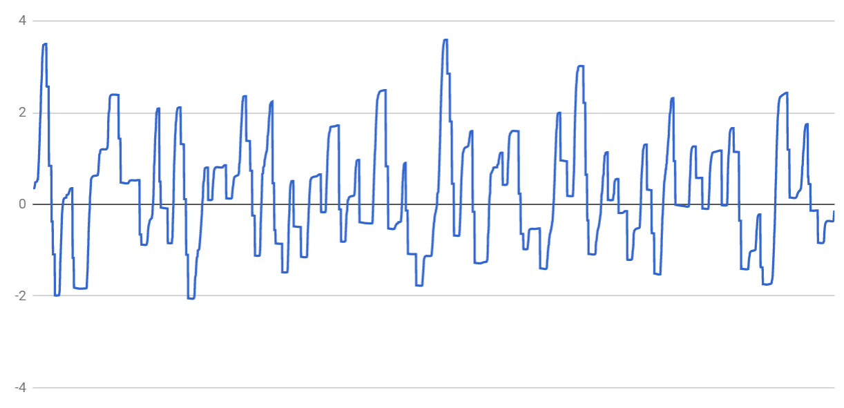
The way it works is that it goes to each encoder position from 0 to ENCODER_CPR-1, and measures the holding torque required to maintain the position. It then uses that as a feedforward term in the control loop. The resulting map looks something like this (courtesy of @madcowswe) :
The results are pretty good. There’s some more things we can do to improve it, such as reverse-mapping, scaling the feedforward based on speed, better memory usage, etc, but it’s serviceable.
To enable anti-cogging, you wait until the motors have finished their startup calibration, then send the command “t” over USB. This enables the anti-cogging calibration, which will run for 5-10 minutes. You may find you need to greatly increase your position gain for this to work reasonably well. I use a 200.0f as a pos_gain with N5065 motors, and it takes ~ 5 minutes to run the calibration. You do not need to keep the high gains when calibration is finished.
Note: The algorithm creates a large array of floats for each encoder, with length ENCODER_CPR. That means using a 600ppr encoder (2400 cpr), it uses 32 * 2400 / 8 = 9600 bytes, or ~ 5% of the RAM per motor. Thus I wouldn’t use TOO high of an encoder count when using Anti-cogging because you’ll quickly be using a significant portion of the RAM.
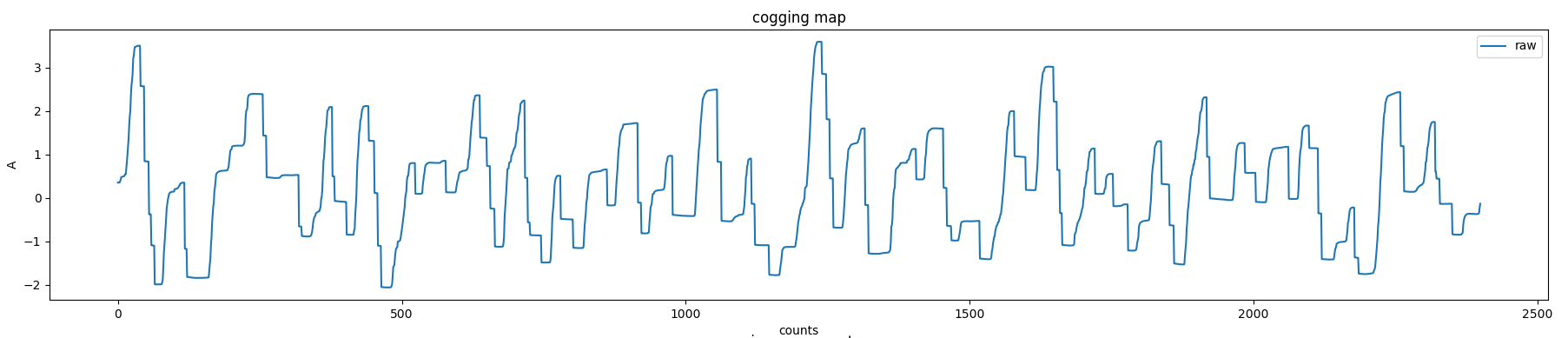
I was able to run the cogging torque mapping algorithm that @wetmelon made. I dumped the generated map via the debugger’s variable inspection feature, and did some analysis in python. Here is the torque map I got (already provided in the above post, but here with units and stuff):
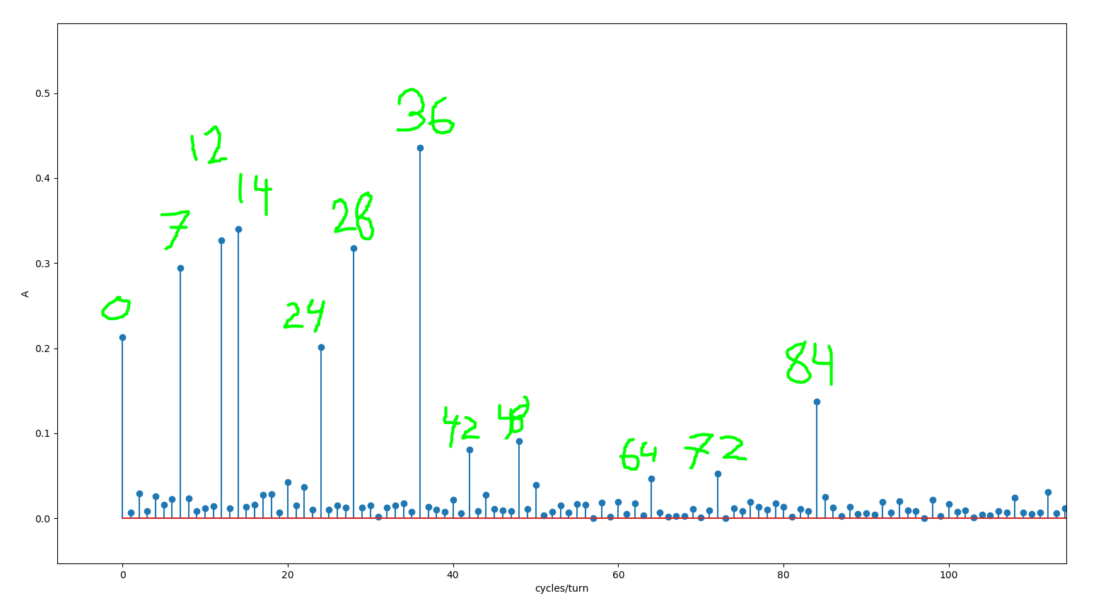
From the symmetry of these motors, we expect that the cogging torque has significant harmonic components at the harmonics of “number of stator slots” and “number of pole pairs”. I took the FFT of the cogging map, and I was pleasantly surprised to find just how crisply these harmonics show up:
The motor under test was the EMP C4250 - 500kv, which has 12 stator slots and 7 pole-pairs. The spikes are at [0, 7, 12, 14, 24, 28, 36, 42, 48, 64, 72, 84]. Except for 64, these are all harmonics of 12 or 7.
Harmonic 0 is the DC offset, and we expect that this bias is present since this calibration scan only went in one direction.
We also see all the harmonics of the number of slots, except that 64 shows up instead of 60. Not sure what is going on there, maybe more data will reveal what’s going on. Anyway, the harmonics of 12 are: [12, 24, 36, 48, 60, 72, 84].
We also see the 1st, 2nd, 4th and 6th harmonic of the pole pair number 7: [7, 14, 28, 42].
I just kind of guessed a heuristic that it’s the 1st and all even harmonics up to slots/2. I am just extrapolating from data here, I have no theoretical reason why that should be the limit.
Nevertheless, here is how the chosen harmonics were picked:
harmonics = [0]
harmonics += [(i+1)*stator_slots for i in range(pole_pairs)]
harmonics += [pole_pairs]
harmonics += [(i+1)*2*pole_pairs for i in range(int(stator_slots/4))]
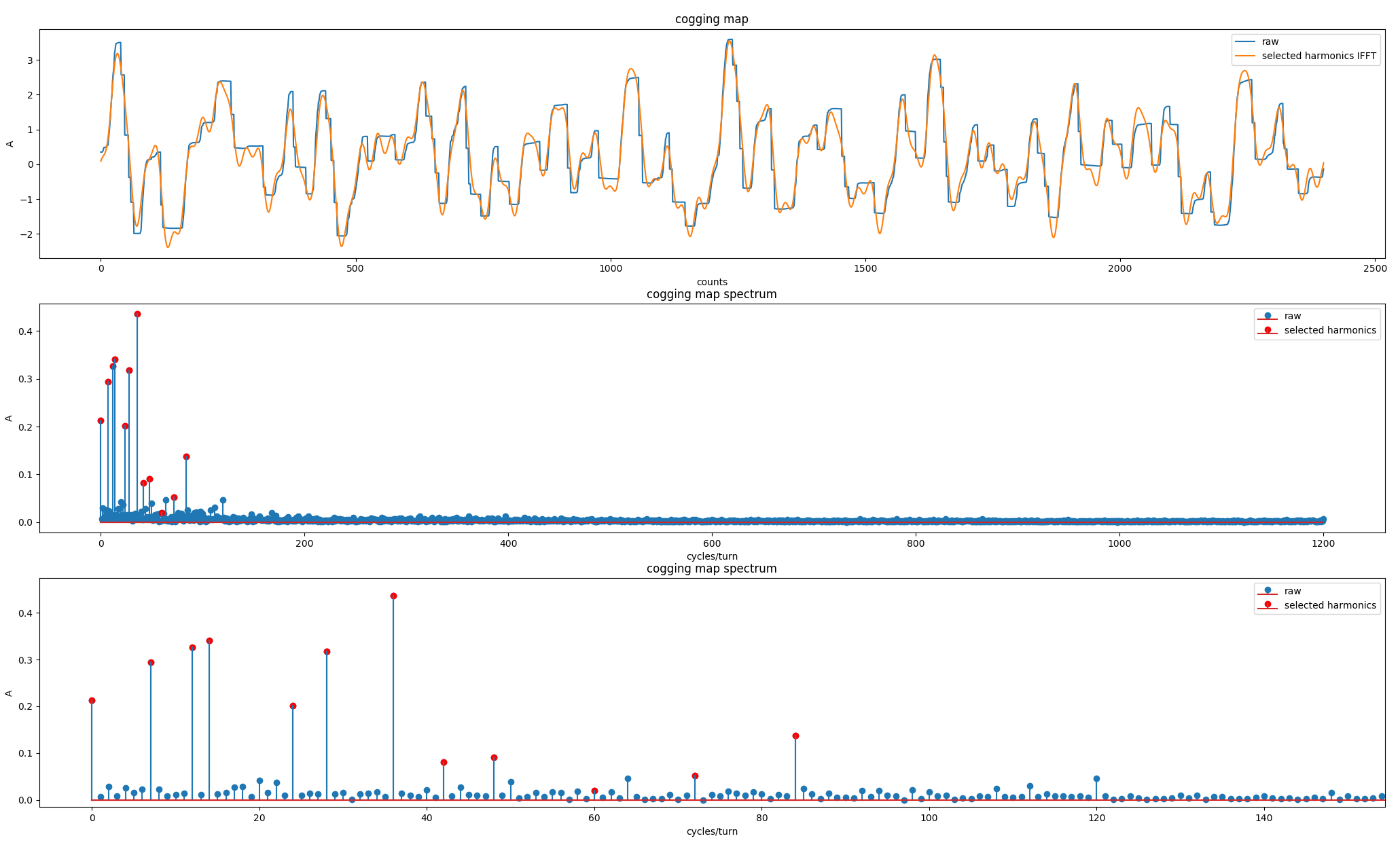
We can generate a “fitted” version of the map by doing the IFFT of only those harmonics. Below you can see that as the orange trace in the cogging torque map (1st subplot). Below you can see a zoomed out and zoomed in version of the FFT spectrum of the cogging torque map, with the selected harmonics in red.
You guys are doing excellent work, as always. Thank you!
I was re-reading that paper and was surprised to see how they handled hysteresis in the forward vs reverse mappings. It appears they just took the average torque from the forward + backward mappings at each point. If you’re looking to further improve performance here and, I’m frankly not sure if it needs it, I’d suggest just selecting from the 2 different directional arrays based on the direction the motor is traveling (maybe based on the sgn(velocity) ).
The downside is that, in this current implementation, this would use twice the SRAM. But if we eventually move to a model-based cogging torque mapping, which wouldn’t need much SRAM, this approach might become more practical.
In any case, I just wanted to share some of my thoughts on this. Awesome work! I’ll be checking it out for myself soon.
Thanks for that. Given the progress on anti-cog does this add to the possibility of realising the control of a two phase system so that conventional steppers may be used in a FOC configuration?
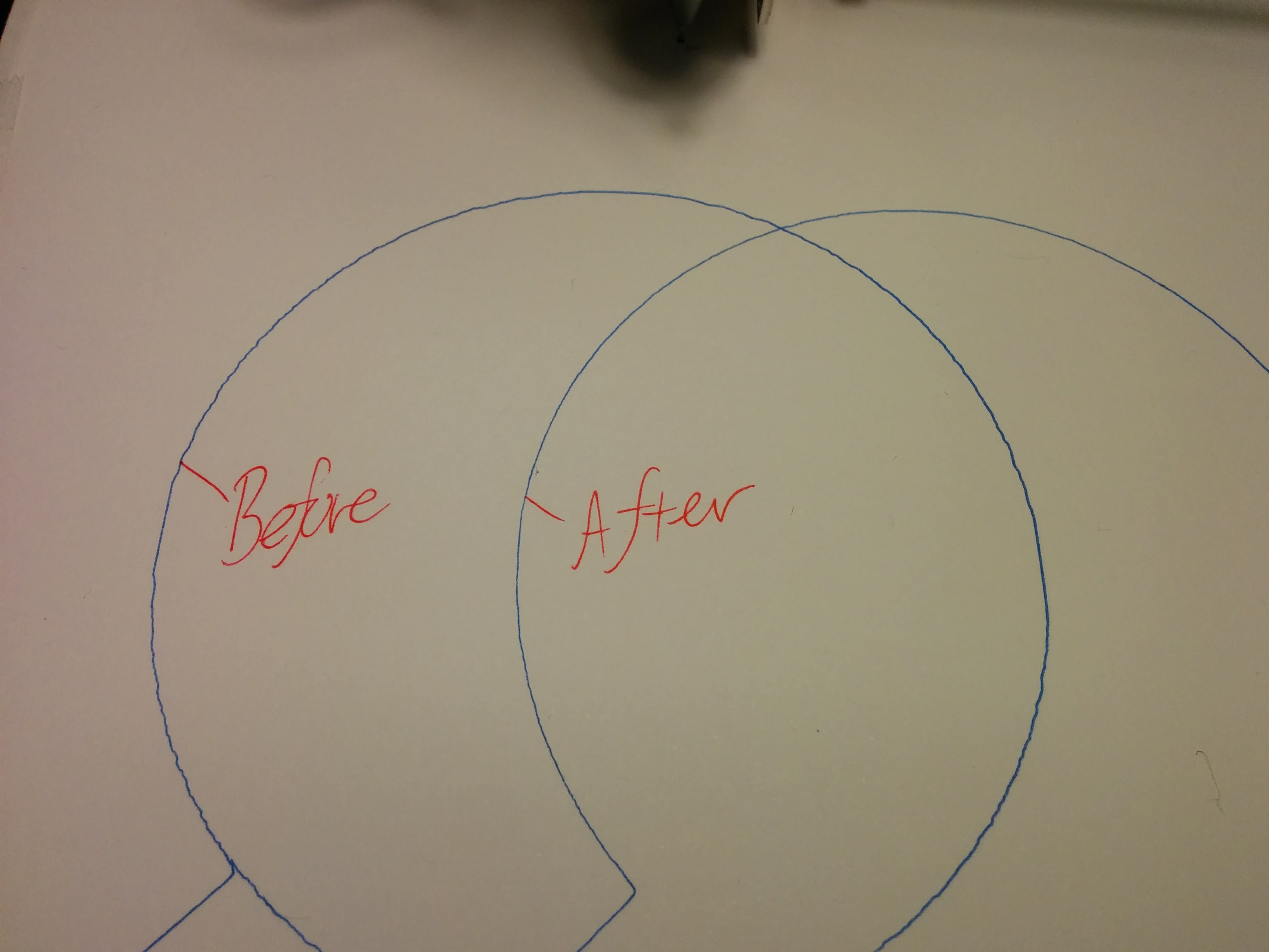
This is using step/dir and 1 step per encoder count with about 100 steps per mm. Pen width is 0.31 mm for comparison. So the cogging was reduced from about ± 0.4mm down to a value less than I can measure.
Just a few notes for those also wanting to test it out. Calibration data is lost after every power down of the Odrive. Calibration takes place on both motors at the same time but I noticed that for my setup one will finish before the other.
I will put some more details about the plotter in a separate post soon.
Ideally this will be used with an absolute encoder that has an index pulse. Then you will only need to calibrate once and the data could be saved. With the incremental only encoders you have no idea where you are/were when power is reset. But this will be a great feature. One of the only real downsides for me on going with hobby BLDC motors. Also if you were to use any gear reduction this will reduce cogging torque effect amplitude at the output by that amount also. Of course the speed will drop but depending on your application more options.
With anti-cogging turned off the motor will be stable (not vibrate) at any position when the appropriate gains are set. With anti-cogging turned on the motor will begin to vibrate by quite different amounts depending on its location relative to a cogged position. In other words, as I step the motor by small amounts, say ~10 encoder count increments, it will transition from stable, to small vibration, to large vibration, small vibration and back to stable as the controller attempts hold position close to a cogging position. Oskar (madcowswe) suggested that applying a smoothing function to the raw measured data may aid in reducing this vibration. A position deadband may also help with reducing vibration while still allowing large gains to be used. Edit: Nevermind, I just realised a deadband would not help in this situation due to the external force of the cogging torque…
If the calibration is done with a drivetrain attached (in my case belt driven linear bearings) then this may lead to any stiction in the system also influencing the calibration curve and so give undesired results. Recommended to do calibration without anything attached to the motor.
If the calibration is done with a drivetrain attached (in my case belt driven linear bearings) then this may lead to any stiction in the system also influencing the calibration curve and so give undesired results. Recommended to do calibration without anything attached to the motor.
Agreed.
With anti-cogging turned off the motor will be stable (not vibrate) at any position when the appropriate gains are set.
Your PID just seems to be tuned wrong. Increase the Kd term and decrease Ki?
So the way it works now is that it uses the current encoder position to do the table lookup for cogging torque compensation, effectively adding terms in the feedback path, and as such it can have effects on the stability. Really what we should be doing is using the position setpoint to look up in the table, restricting the cogging compensation to be in the feed-forward path only. I put a task in the roadmap about it.
@madcowswe have you seen the CUI AMT20 encoders? 4096 position absolute and not that expensive. If I’ve understood correctly they are absolute from power on. There is an incremental and index output but I believe that’s just an optional extra. Absolute position is via 12 bit SPI message.
These would be ideal once the startup procedure and anticogging lookup can be kept in non-volatile memory. The ODrive could be fired up with whatever gubbins it is attached to and deliver commutated, anti-cogged torque instantly with no startup proc
They are available on mouser.
Re your comment on using set point for anti-cogging lookup table, obviously it would need to keep using the encoder in torque command mode, so please don’t remove that option!
Yes I saw those, @aksatshah is actually working on a driver to read the absolute position at startup, and run on incremental from then on. They are a fair bit more expensive than the AMT10 series, but if doing the start-dance to find the index pulse is not acceptable, then they seem like a good option.
Yes I see the point. I think we can use the position setpoint during position control mode, and the encoder position for lookup in velocity and current control modes.
Yep correct you are! I am working on that and I believe its all working although I’ve had to change my rig so cant fully test it now. I had some issues with noise on the SPI line but I was only using it to get the absolute position at power on and then using the incremental output for the rest. It also depends how fast you want to read the data. I believe I was only getting the position at a rate of 1kHz but maybe this can be improved with some extra work on overlapping commands. The biggest problem is the encoder isnt always ready to transmit the absolute position straight away and so usually sends 2-3 nop commands and you have to wait, but with overlapping commands we should be able to remove this issue.
Let me know how it goes if you do use it and if you have any problems etc.
@tobbelobb Hit me up on the ODrive Discord when you are about to start working with this. The anti-cogging feature is just a proof of concept at the moment, and not really a full feature. So you may need some guidance to get it to run properly. If it turns out it makes a big difference for the hangprinter, we can put some priority in finishing the feature to make it easier to use.
")