Balance Control with Encoder Feedback

Hi,
I’m trying to reproduce a certain feature of this robot:

As you can see there, the robot moves onto a ramp with one leg and doesn’t get pushed to the side. The way I see it, this control feature cannot just depend on an imu sensor, because there is no visible rotation to the side. It must control the leg in response to the measured force in the knee.
What would be the best way to implement this with ODrive?
I don’t know much about control theory, but if someone can point me to a specific direction, I’d really appreciate it.

best regards!

These kind of robots tend to be controlled in torque mode on all actuators. So the controller is not sending position or velocity commands to keep it upright, but torque commands.
Using a Jacobian transform, you can map actuator torques to end-effector force.

But it’s not so simple to make a Boston Dynamic style robot - you cannot make a robot balance robustly like this without updating the torque/force commands inside a pretty complicated model-based controller. Usually this is made by training an artificial neural network using simulated physics.

e.g. take a look at how ETH Zurich did a similar thing: Learning Agile and Dynamic Motor Skills for Legged Robots - YouTube

Thanks towen!
Your suggestions definitely steered me into the right direction (I think) :slight_smile:

I have a first version working. It’s not perfect, but the balancing on the ramp works good enough for now. I have the problem though that the controller ist not stable yet. After a short time, it always results in oscillations that cause the robot to fall to one side. I also have a pretty good idea why these oscillations occur, but I don’t know how to fix them. Maybe you or someone else here has an idea. Unfortunately I have to elaborate a bit to explain the problem, but please bear with me:

So like you suggested, I calculated the transformation and the jacobian, that map the two knee actuators to these two values:

  • The resulting robot angle (assuming the ground is flat)
  • The average height

Because both knee actuators are connected to the same ODrive, I’m able to do this calculation on the ODrive itself. I then also added a simple PD controller with separate gains for the robot angle and the height.
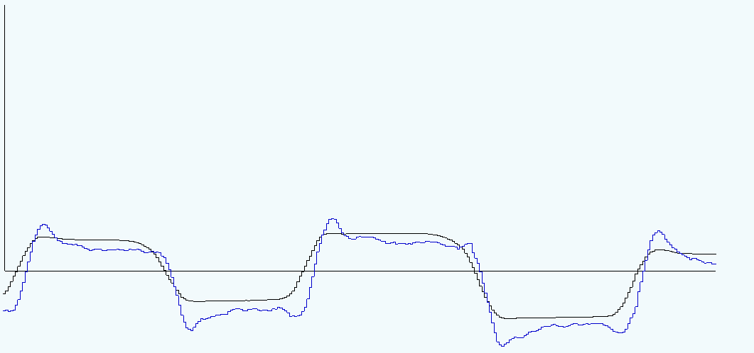
So far, this works great and if I, for example, set the gains for the angle to zero, the robot stays at the same height, but is freely movable to either side. Here is a plot of a run, where I did that:


What you can see here is the robot angle, as calculated by the joint angles, in black. (This is calculated on the ODrive)
Plotted in blue is the imu angle reading. This is only sampled with about 50Hz, because the imu sensor isn’t connected directly to the ODrive.
Because both wheels stayed on the ground in this run, you’d expect both values to be about the same, but you can see that the imu sensor lags a bit behind and also seems to overshoot a bit.

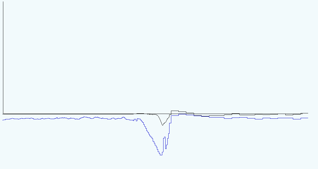
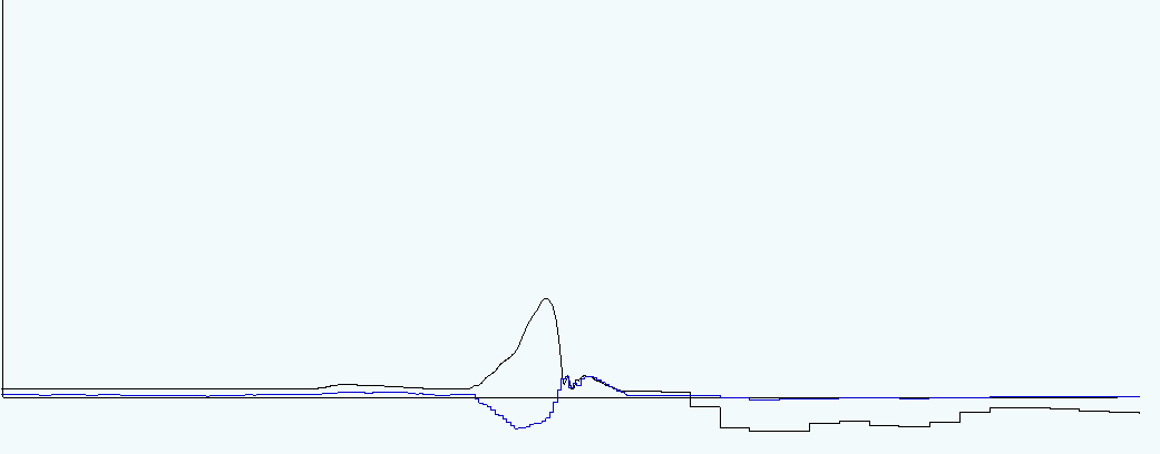
For comparison, here is a run, where I enabled both gains (so the robot tries to keep the leg lengths the same):


In this run, I moved the robot over a ramp, such that one leg is lifted, just like in the video in the first post. As you can see, the robot angle is successfully kept very close to zero (the small displacement is from the fall at the end of the ramp). And the imu sensor shows how the robot moves to the side, as it goes over the ramp.

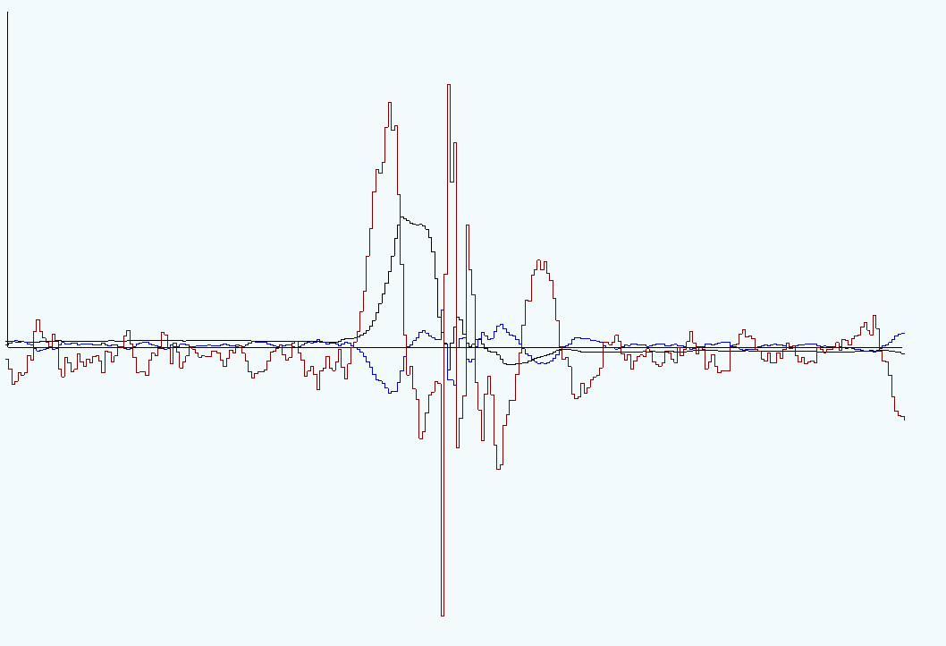
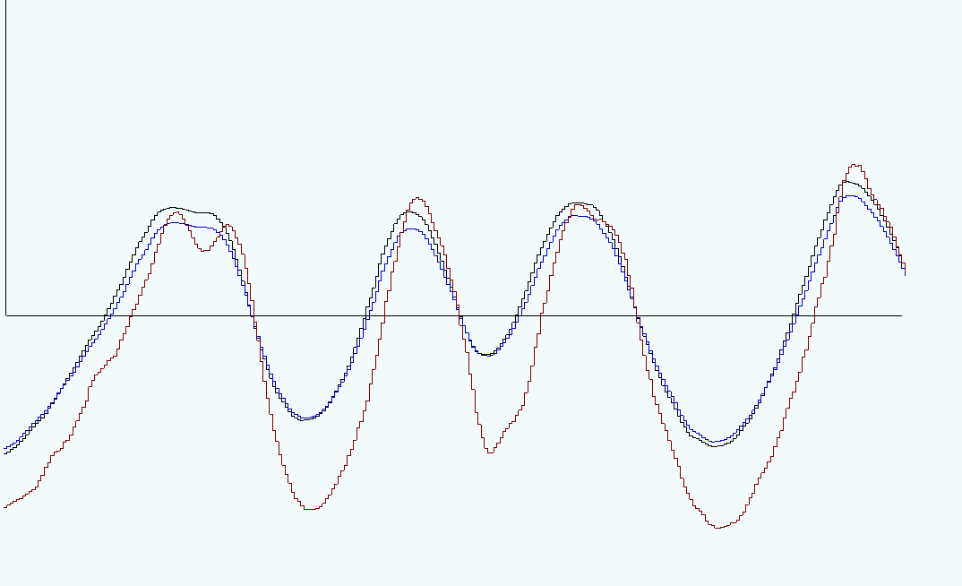
Ok, now to implement the balancing as shown in the video, I changed the force, that is applied to the robot angle in such a way, that the imu sensor is kept close to zero. A lot of trial and error showed, that a high p value, a low d value and zero i produce the best results. Here is one run:


You can see, that the imu sensor value (blue) stays kinda close to zero and the robot angle (black) successfully compensates for the ramp. I also plotted the force, that is applied to the robot angle in red here.

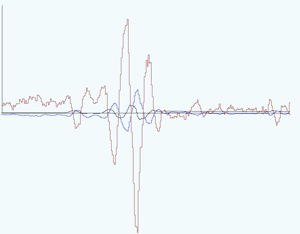
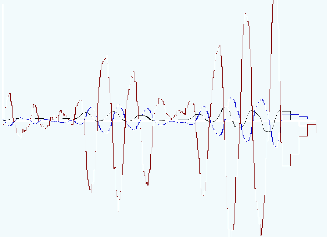
So, this works all great so far. Now we come to the problem. Here is a run with no ramp:


You can see, that an oscillation starts out of nowhere. It then stops, but only because I then start to hold it tight to prevent a fall.

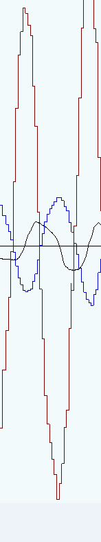
Here is another oscillation

Now the reason for this seems to me to be the delay of the imu sensor (blue and black should be about equal here). You can see that the frequency is such that the force (red) aligns with the derivative of the robot angle (dt of black). But how do I prevent this?
I don’t think I have cpu time left on the ODrive to read an imu sensor there directly, and I’m not sure if that would prevent the delay.
If I reduce the P gain or increase the D gain of the imu pid controller so much that the oscillations stop, it also stops being effective on the ramp.

So, sorry for the lengthy description, but I’m sort of stuck on this problem right know. I’m happy to share more details if requested.

1 Like

Interesting post! :smiley:
So, if the IMU is not connected directly to the ODrive, how is it connected, and why are you limited to 50Hz?
It may be that most of your delay is coming from the sampling rate i.e. you need to wait on average 10ms per sample.

Probably, you do have enough CPU time to read it on the ODrive - it’s just an SPI sensor, i’m assuming? So, same as a SPI absolute encoder that ODrive already supports.

If you want to profile CPU usage, the dump_timings(odrv0) command is really useful - it saves a PNG with a graph of CPU usages of various parts of the program. You can probably add your own code to this profiler if it doesn’t come in automatically.

It’s also an interesting problem, and I admit I didn’t think it would be so difficult to implement :slight_smile:
So there are two ODrives in the robot, both controlled by a Jetson Nano, connected via UART Native Protocol. One ODrive controls the knee joints, the other one the wheels on the bottom. The imu sensor is required to control both ODrives, so I figured it would make the most sense to connect it to the Jetson Nano and have it control the ODrives. The wheels are controlled in velocity mode and a simple PID controller and that works perfectly.
I’m limited to 50Hz on the Jetson because communication with the ODrives via UART is quite slow. I already optimized the number of requests and increased the baudrate to the maximum that works. If I switch to CAN, I might be able to improve this, but I’m a bit hesitant to do this. I’d have to change a lot of code because there is no native protocol support via CAN (it would probably be easier for me to add that support myself) and of course I’d have to rewire everything.
I also don’t think that increasing the sampling rate is going to help. If you look at the plots above, the steps you see are caused by the low sampling rate on the Jetson. That is each line is about 20ms. The black line has these steps too, but only because I generate these plots on the Jetson and the Jetson usually only samples these values from the ODrives with the same frequency as it does the imu sensor. But with the oscilloscope feature I was also able to get this part:


Due to the low amount of RAM in the ODrive, I only get less than a second of data in such a run, but everything you see here comes from the ODrive at 8kHz (I modified the firmware such that the oscilloscope records multiple values).
And well, you can see there that the delay of the imu sensor data is about 10 Jetson sampling steps. So increasing the sampling rate would probably smooth that curve out, but not fix the delay.
Now where is the delay coming from? I have no idea :slight_smile: But I was hoping that I can somehow work around it in the control loop

OK, I figured it out :slight_smile:

In case anyone is interested: The imu sensor data was not delayed. It only appeared to be delayed because the sensorfusion code that calculates the final angle wasn’t calibrated correctly. It was putting too much weight to the accelerometer data and not enough to the gyroscope. Calibrated correctly, you don’t see any delay between the robot angle (black) and the imu angle (blue):


(The red line is the old imu sensor fusion code).

With this fixed, the oscillations are completely gone, and I was even able to increase the gains. This is the ramp movement now:


This imu deviation is less than 3° and not really visible.

2 Likes