Hi,
I’m looking for a 24V brushless motor that can turn at 500-700 RPM and have a torque of 1 N.m.
Can someone send me a link, I have some difficulties finding one.
Thank you
Hi,
I’m looking for a 24V brushless motor that can turn at 500-700 RPM and have a torque of 1 N.m.
Can someone send me a link, I have some difficulties finding one.
Thank you
Look for any motor with a low ‘KV’. This is the back-EMF constant (rpm/V), and is inversely proportional to the Torque constant (Nm/A)
For example, a motor with KV = 100 has a torque constant of about 0.1 Nm/A. So if you run it at 10A it will produce 1 Nm. At 24V your speed limit would be 2400 * 80% ~= 2000 RPM which is well within your spec of 700 RPM.
Whereas a motor with KV = 200 will produce approximately 0.5 Nm at 10A, and it could reach 4000 RPM at 24V which you don’t need.
Try “X8308S” - these come in a size that can be wound at KV100 and can take about 20A i.e. 2 Nm max.
Thank you, but 2000 RPM is too fast for my application, can I run this motor with a PWM of 25% to have the good speed (2400*25% = 600 RPM) ? Also, would it affect the torque if I have a PWM of 25% ?
Yes of course, that’s what ODrive is for - it regulates the current to produce the required torque, and regulates the torque to produce the required speed / position.
2000 rpm is only the maximum possible speed with this motor, 24V, and no load.
At 600 rpm it will easily be able to produce the 1 Nm that you need.
I’m still learning alot about brushless DC motors, but is it not the case that the rotor rotates in sync with the rotating magnetic field? So I sort of thought that speed control would simply be rotating the field with the correct speed. And the torque would self regulate itself (in proportion with the angle between field and the magnet pole)?
Err no, not quite. 
The only fundamental relation in a motor is between current and force, and in a rotary motor, force is in two dimensions: radial aka ‘direct’ (which produces no torque) and tangential aka ‘quadrature’ which produces torque.
And a motor is an AC machine. “There is no such thing as a DC motor” btw. (well, there are certain exotic DC linear motors i.e. ‘railguns’, but I digress…)
In a “brushed DC motor”, a mechanical commutator is used to reverse the flow of current in the winding as the motor turns, so that the torque is always in the same direction.
In a (crude) BLDC motor controller, Hall sensors are used to measure the angle (to within the bare minimum of precision) and drive MOSFETs to reverse the current in the coils, emulating a mechanical commutator.
In FOC (Field Oriented Control - the control scheme that ODrive uses) an encoder, or sometimes a “sensorless phase estimator”, is used to measure the precise rotor angle, and current sensors are used to measure the current in the coils. High-frequency PWM MOSFETs vary the (average) applied voltage to the coils, and a very fast control loop, using the motor’s inductance like an electrical inertia, is used to vary the PWM duty to control the current so that a) the magnitude of the field is always regulated to be proportional to the requested torque, and b) the phase (i.e. orientation) of the field is always tangential to the rotor, and so produces maximum force in the tangential (Q) axis, and minimal force in the radial (D) axis. This involves some maths called a D-Q transform (aka Park’s transform) and this is what ODrive spends most of its CPU cycles doing. It’s the most efficient way to control a brushless motor, and is the only way that produces a (nearly) linear torque response even at stall, i.e. even at zero speed, we can still control the torque in the motor.
If we are in velocity mode, ODrive wraps another control loop to vary the torque to try to regulate the speed to the requested setpoint. And in position mode there is a third loop that acts on the velocity demand to keep to a position setpoint.
See Control | ODrive
It’s possible to move a BLDC motor simply by feeding it a fixed AC frequency just as you describe though, and indeed that’s exactly what the ODrive does during its calibration sequence before it has any phase information from the encoder. But this way is weak and inefficient, and as soon as you get near the point of maximum torque, you would be in danger of going over the hill and pulling in reverse towards the other magnet. A bit like when you over-torque a stepper motor. You can try this yourself by feeding a fixed DC current from a bench power supply into your motor: It will seem to hold position, but you can easily displace it, and if you displace it too much it will snap to another position.
So if the motor simply rotates “in sync with the field”, then most of the force is in the direct (radial) axis, and it is extremely inefficient at producing torque. This is one of the reasons why we have to do the calibration without a load connected.
To produce torque, the field needs to “lead” the rotor. It can’t be simply “in phase”, because otherwise the coils would just be pulling radially against the magnets.
Hi Towen,
Thanks for replying in such detail, I really appreciate it.
Hope you don’t mind to ask a few more questions, If you prefer that I PM you let me know please, feels like I am hijacking this thread a bit.
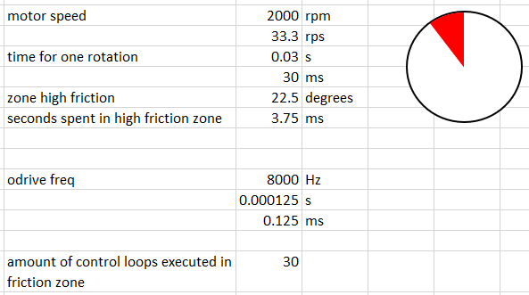
But, taking the example above for a motor that could reach 2000 rpm. If I assume that during one rotation of the motor, there is a small angular zone (let’s say 22.5 degrees) where the motor experiences more friction (for some reason).
Some quick calculation show that the motor would only spent 3.75ms in that zone. The controller works at 8kHz, so it will execute 30 loops in that time.
Can I assume that this is a very difficult task for Odrive to keep the speed constant in such a case? If not impossible? I suppose as the rotor enters the high friction zone, the controller will start to increase the torque to keep the speed constant, and as it leaves this zone it has to lower the torque again to avoid the rotor spinning too fast? But doing this at 2000rpm would seem … not feasible?
Also if you could recommend a good book that is accessible and clear to improve my knowledge in this area, please feel free to suggest. (I’m a bit ashamed to say that I actually should know all this stuff already, I had multiple courses on motors and control back in uni… But those courses where highly theoretical and I failed to really grasp the material. And not having needed this at my job (for 10 years now) has not improved matters at all. Currently trying to relearn everything again, mostly in my free time, and to really “get it”  )
)
At 2000 rpm the motor’s own inertia should be more than enough to smooth out the torque that the ODrive needs to apply. The inertia produces a torque proportional to acceleration, and the energy stored in that flywheel effect is proportional to the square of velocity.
If the mass is concentrated at the edges, (which in an outrunner motor, it usually is i.e. the magnets and their back iron) then the inertia itself is roughly proportional to the square of the radius iirc.
But you are right, at low speeds it will be an issue, depending on how severe the friction. But the ‘integral’ gain on the velocity controller should ensure that it doesn’t get stuck.
I have never read any books on motor control since uni either… 
Like Tom said, it should work pretty well due to the inertia alone. What % accuracy do you need? A higher encoder resolution helps a lot here.