I’m thinking about buying this Staubli TX60 arm and building a controller for it. I’ve not found any documentation for the controller/arm interface so I’m not sure how feasible this is. Has anyone else tried doing something similar?
Do you know what voltage the motors are designed to run at?
Most industrial robots use rectified mains (300-350V DC) as their DC bus, and therefore the motors normally have quite high resistance & inductance (high EMF constant) compared to motors designed for 24-48V DC Bus.
You can sometimes drive a mains-rated motor with a 56V ODrive, but it’s max speed will be much reduced, max torque and controllability probably also reduced.
Also, does it use encoders or resolvers? Most encoders can be adapted to work with ODrive (they almost certainly won’t work out of the box, they will be SSI or at least differential) but resolvers will need specialised analogue front-end ICs (“resolver to digital” aka “R-D converters”) to read.
The motor specs were surprisingly hard to find, but I think this one of them:
Which says 200V, 17A (peak). That’s from a different model, and I’m not even sure if every axis is the same.
The actual wattage seems within the range of an ODrive, I wonder if something like a boost converted to increase the voltage would work here (caveat: I have only the most minimal EE knowledge).
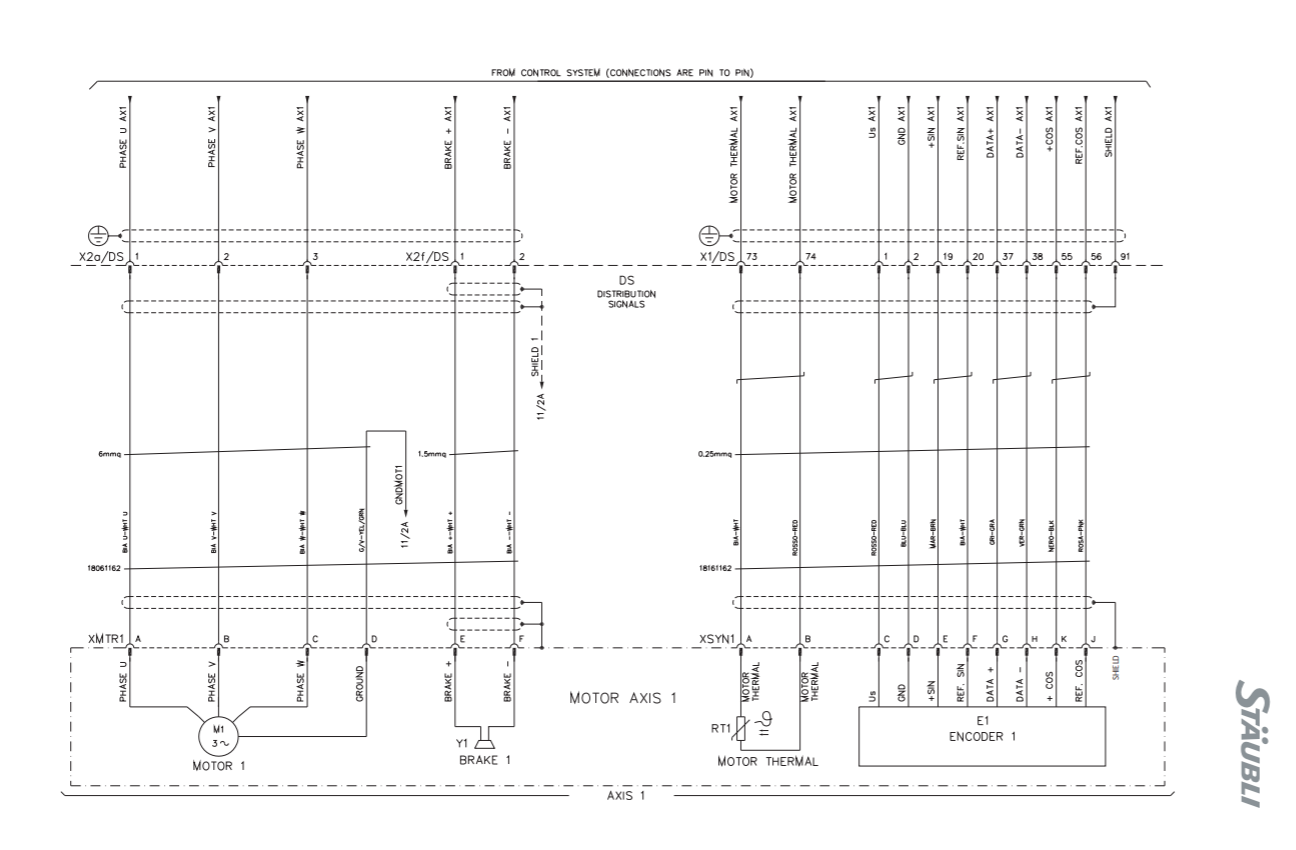
The maintenance manual’s electrical diagram does show encoders:
Any idea what the resistance of the winding is?
Also, that encoder looks problematic. It only has DATA +/- but no clock, so it’s not SSI. It might have some proprietary async serial (RS422) interface, at least for the absolute angle om start-up. Then the dynamic angle is given by the sin/cos, which might be analogue or incremental digital, but in any case it won’t be straightforward to interface to ODrive. 
Do you have an oscilloscope that could probe the DATA and sin/cos signals?
I don’t actually have the arm in my possession so not sure about that. I’m tempted to just buy it and see what I can do though, it’s relatively inexpensive vs other stuff I’ve found. Maybe I could mount a new encoder on it or something.
How feasible do you think the idea to use a boost converter to bump to 200v is?
Not feasible at all, i’m afraid.
A boost converter can step a DC voltage up to a higher DC voltage. So if you had a 200V capable ODrive, then you could use a boost converter to run it from a 12V battery.
But a boost converter cannot convert the mix of DC and AC that is what a Permanent Magnet Synchronous Motor runs on. (nor even could an AC transformer)
A “brushless DC motor” aka PMSM is not really DC, but synchronous AC, - synchronous not with time, but with angle. That’s what the ODrive does, converts DC to position-synchronous AC, using an encoder to sense position.
But the ODrive is designed to work with low voltages and high currents. The MOSFETs (and more crucially, the gate drivers) are limited to 56V DC supply, and going higher than that will damage them.
It’s possible that there will be a high voltage ODrive in future that will be able to use these motors to their full ‘potential’, but for now you would have to put up with low speed and torque.
Note: It’s quite likely that you would still achieve the full “stall torque” of the motors, but the torque capability would drop off quite rapidly as the speed increases. So as long as you don’t mind a slow robot, it should still be fairly strong.
Is speed proportional to voltage, like the motor KV rating? So e.g, motor specced at 200v run off of a 56v ODrive would run ~1/4 the speed?
Yes it would, but you also need to consider the motor’s resistance, which will also limit how much torque it can produce.
It’s unlikely that the motor would ever reach its max speed in normal operation, the safety joint speed limits will be much lower than the motor’s max speed. It’s perhaps around half, probably less. Industrial robots are designed to have a lot of voltage headroom.
But, power is limited. Suppose your motor is running at a speed where the back-EMF is 24V i.e. 1/10 of the motor’s max speed, 1/5 of the robot’s max design speed.
Now, you only have 26V (of a 50V supply) left to overcome resistance. If you were to go faster, you would have less torque available and control performance would suffer.
Supposing the winding is 1 Ohm and you need to supply 20A for the torque you want. That’s 20V dropped across the resistance. Now you only have 6V left as a headroom.
This headroom is important because you also need to overcome inductance to have good control performance. Supposing you need to bring your robot to a stop or change direction suddenly. You want to go from +20A to -20A as quickly as possible. - Let’s say you want to change it in 1ms and the motor’s inductance is 500uH. V = L dI/dt ; dI/dt = 40 kA/s ; you would need a further 20V headroom to change the current this quickly, which you don’t have.
Also, high resistance motors can cause a problem with ODrive - there are many threads here on using ODrive with a high-resistance motor - mainly it involves changing the current sense shunt resistors.
And finally, you need to be careful that you don’t back-drive the motor and destroy the ODrive by overvoltage.
1 Like
I found a controller board that supports high-voltage motors, up to 320v / 2.2kW, and there’s at least one example of someone driving this specific arm with it.
And an example in action: Open Source Robot Controller Running GCode on Staubli RX60L - YouTube
1 Like
Would you mind going a bit further on this topic? What kind of overvoltage could hurt the Odrive? I’m curious because I’m currently trying to design a cobot, and I would like to have the ability to pull/push the arm, so I will be backdriving the motor for sure…
If you were to use the ODrive to move the arm as fast as it possibly could, it would eventually reach a certain speed (where the back-EMF ~= DC Bus voltage) where it cannot go any faster.
If you were to manually force it to go faster than this speed (with DC supply on OR off), then you could over-voltage the DC bus through the MOSFET body-diodes.
If the supply is on, then the ODrive can protect itself from overvoltage with the brake resistor.
The drive can no longer be made because the integrated gate module was discontinued years ago.
You’d need to re-engineer it with a new one.
the integrated gate module was discontinued years ago.
What does that mean?
I think he’s referring to this component: https://www.mouser.co.uk/ProductDetail/Infineon/IRAM256-2067A?qs=sGAEpiMZZMtJbfcMcIM8CBauSGEUOnhEVjD9LAMi10o=
Lifecycle: Obsolete. Availability: Not available. (and it never will be)
But if you are willing to redesign the PCB it should be easy enough to replace that with discrete IGBTs and half-H drivers.