Hi, I am using V3.6. I purpose is to connect 2 Odrives with my Raspi .
Data definition table
Where can find command data definition?
for example:
I found in source code example.
AXIS_STATE_CLOSED_LOOP_CONTROL (0x08).
AXIS_STATE_FULL_CALIBRATION_SEQUENCE (0x03)
is there any table which show 0x08 = closed loop control?
I found the command ID table in Doc. but nor find the data definition table.
2.Node ID problem
should we also also set Raspi node ID?
I hope 2 Odrives send back their pos to my Raspi when after they arrive their request pos,
it means each Odrives will send to the same ID(Raspi), it will cause conflict??
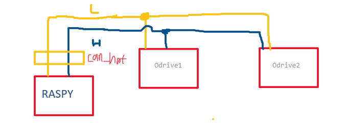
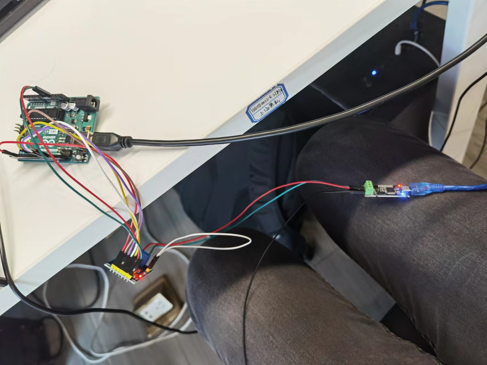
connection
I want to using raspy to connect 2 odrives.
is it a correct cable connection below?
can_helper.hpp
do you provide a demo about how to use can_helper.hpp, because I want to use Arduino&cpp to
communicate with Odrive.
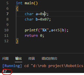
can_ID
I found on other website, they use 0X207 as Can_id, node_id is 0x02, cmd_id is 0x07
that is very confused for me, if node_id is 0x02, cmd_id is 0x07, so 0x02<<5|0x07 will be 0x47 but not 0x207, is there any misunderstand on this.
Yes, in the docs. The enums have been updated over the years to be AxisState.CLOSED_LOOP_CONTROL.
No, the ODrives are not sending data “to” the raspi, they are putting messages on the bus, it is up to the raspi script to filter and process these.
To get the encoder position you can either:
Request Get Encoder Count with node_id << 5 | 0x00A (make sure you set the RTR bit)
These messages are call & response. The Master node sends a message with the RTR bit set, and the axis responds with the same ID and specified payload.
Alternatively, all “Get_” messages are cyclic, so you could just set encoder_count_rate_ms.
Nothing looks wrong, but it is also very important to get the grounding right. Please refer to our wiring diagram for more details.
Not that I am aware of, you can checkout this repo to see it in use though.
Yes, 0x02 << 5 | 0x07 = 0x47 is the correct message ID, it looks like this other website simply concatenated 0x02 and 0x07, which is wrong.
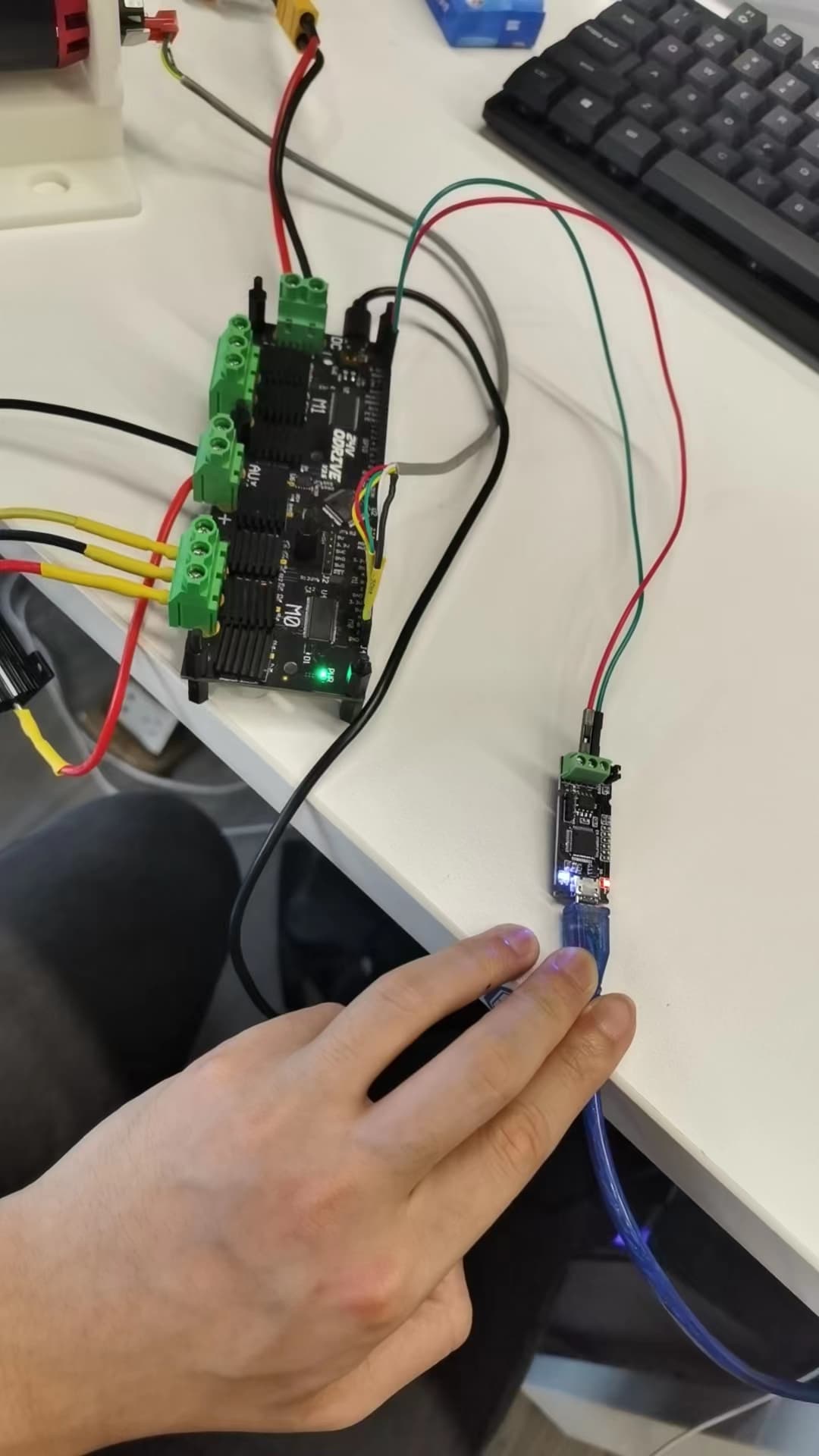
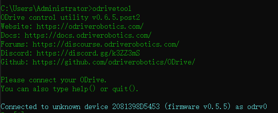
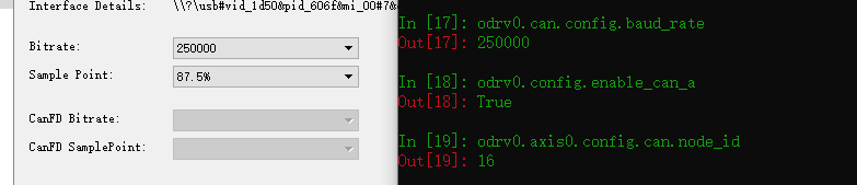
I bought a can_to_usb device to connect the Odrive with PC to test the heartbeat message, if I can receive.
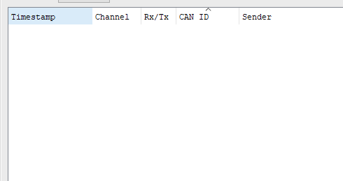
but there is no message from odrive to can_hat.
I used a software named “cangaroo” to monitor in PC.
for check the reliability of my can_to_usb, I used my arduino_mcp2515 to communicate this can_to_usb, it really works, so I had a little lost in this point.
for the problem 5, yes, the website made a mistake, they set odrive id =0x010,(which is hex) but they mention set ID=2, this is wrong, ID should =16( in dec). hope it can help other dudes.
Okay cool, I’m glad its working now.
Not having the common ground point will impact the reliability though, make sure this is connected before going too much further.
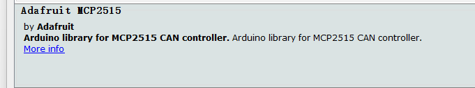
I’m using the same system as you, but I still haven’t figured it out. I think I have a library problem. Which library do you use for MCP2515 . Can you share the Arduino code?
I’m also trying to communicate with the Raspberry Pi4 via CanBus. I’m using the RS485/CAN HAT module but I haven’t figured it out yet. I made all the settings but I couldn’t get any signal. On the Odrive, the node ID is 0x1, bitrate 500000. In Raspi, the settings are crystal oscillator 12000000, bitrate 500000. But whenever I use the candump can0 command, I do not get any response. The cansend command is the same way. Is there a problem with Node ID? I also tried the can_dbc_example.py I got this response:
pi4@pi4:~/ODrive-fw-v0.5.4/tools $ python3 can_dbc_example.py

Requesting AXIS_STATE_FULL_CALIBRATION_SEQUENCE (0x03) on axisID: 1
{'Axis_Requested_State': 3}
Timestamp:        0.000000        ID: 0027    S Rx                DL:  8    03 00 00 00 00 00 00 00
Message sent on socketcan channel 'can0'
Waiting for calibration to finish...
However, I also get this response when Odrive is not connected. I understand there is also a problem with my Odrive connection. I don’t know what I’m doing wrong. My connections are CanH to CanH, CanL to CanL and GND to GND between odrive and RS485/CAN HAT module. 120 ohm switch on Odrive side. There is 120 ohm include resistance on the HAT module. But nothings happen.
When I try to communicate between Raspi and Arduino, I can send and receive messages, but I could not establish this relationship with odrive.
