CAN Bus Failure w/ ODrive S1 and USB-CAN adapter

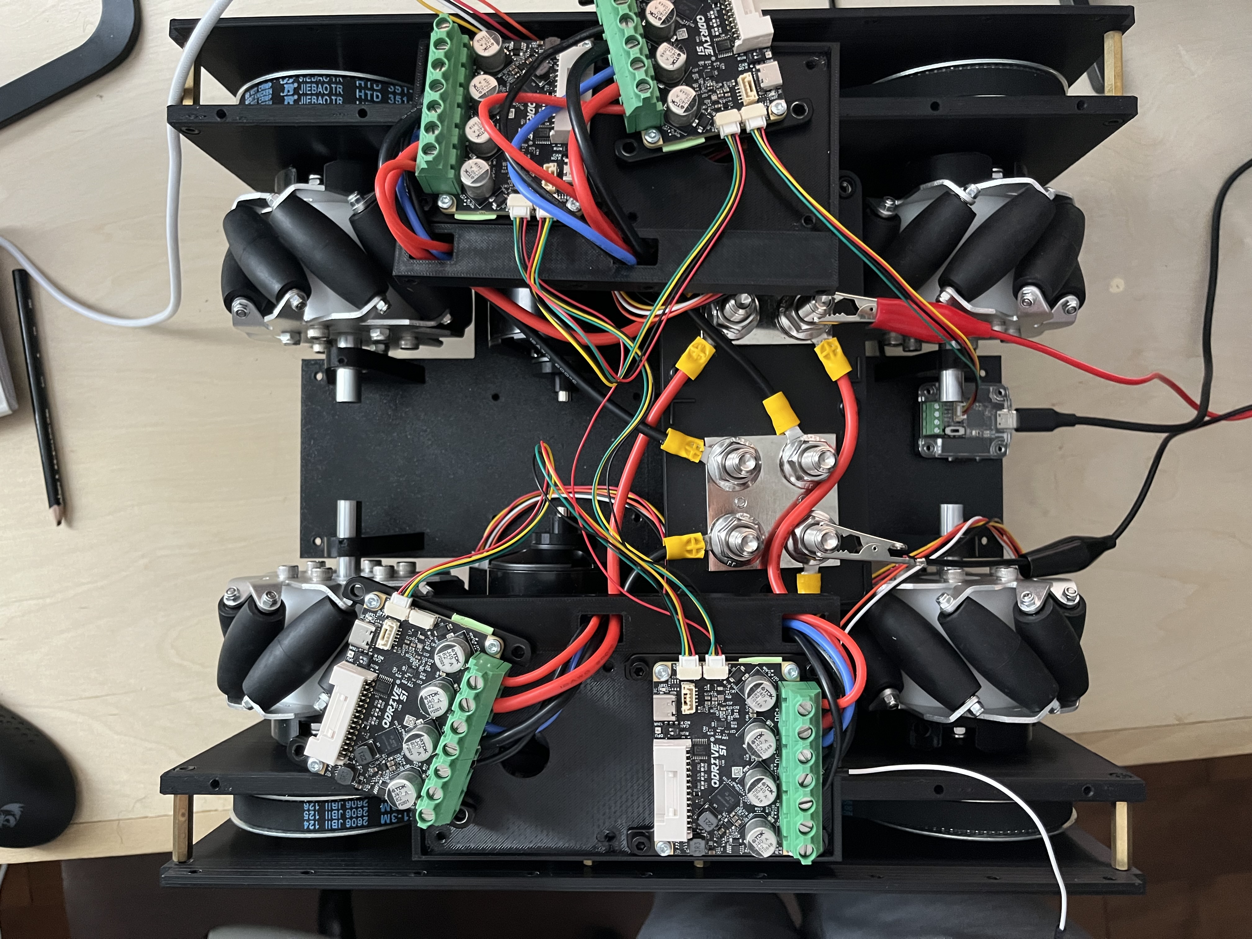
Hey everyone, new to ODrive robotics here. I’ve got 4x ODrive S1s that I configured over USB successfully, and I’m now trying to get them running over CAN using the ODrive USB-CAN adapter.

My issue: only the 2nd and 3rd ODrives in the chain ever show up in the Web GUI or on Linux and Windows.

I’ve tried:

  • Swapping which ODrives sit in each position. All ODrives work in position 2 and 3
  • Confirmed unique node IDs
  • Toggling the termination resistor on the last ODrive, and every combination of onboard resistor infact. Resistance is 60 ohms
  • Grounding the CAN bus
  • Confirmed proper power on all ODrives
  • Swapped bus wires around

It is always position 1 and 4 in the chain are the problem. Anyone seen this before? Any help appreciated!

Edit: did some more reading and it appears some related software is new. Is this the issue?

That’s interesting! Could you share some pictures of your wiring?

Yes. Diagram or actual?

Both would be great!

Amazing.

Here are both.

Note: the JST cables aren’t twisted yet as I just received them, but I’m assuming that would only cause noise, not the extent of my issue.

Also, some onboard resistors are switched to the incorrect positions. This was for testing and have since been corrected. Problem persists.


Hopefully these are easy to follow. If not, I can take better pictures/make another diagram.

Thanks again!

Thanks for the pics!

It looks like the pinout ordering is swapped?

On USBCAN you have (from what I can see, a bit blurry),
Red: VBUS
Black: CANH
Yellow: CANL
Green: GND
image

But then on the upper right ODrive, you have:
Red: GND
Black: CANL
Yellow: CANH
Green: VBUS
image

And then the cable pinout ordering swaps again between the upper right and upper left ODrive:

Then it’s the same between upper left and bottom right:

But then it swaps again between bottom right and bottom left:

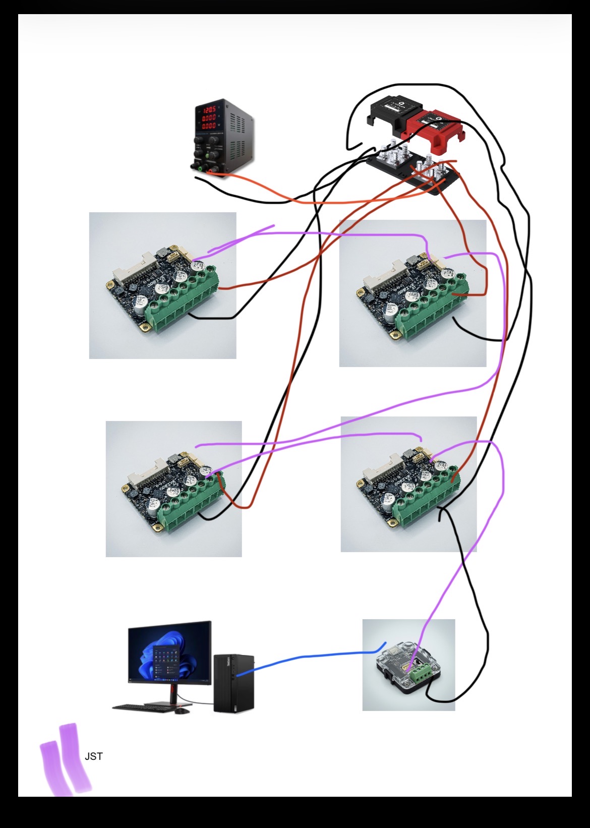
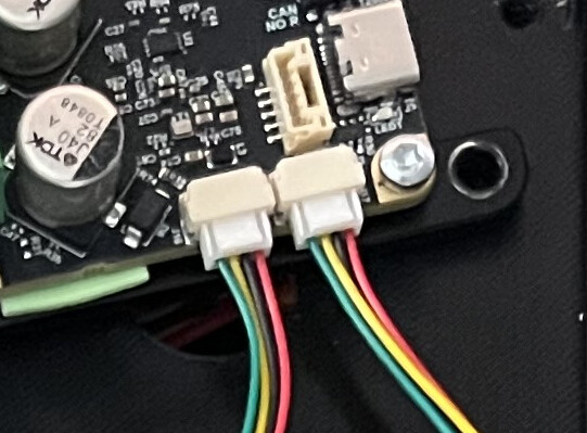
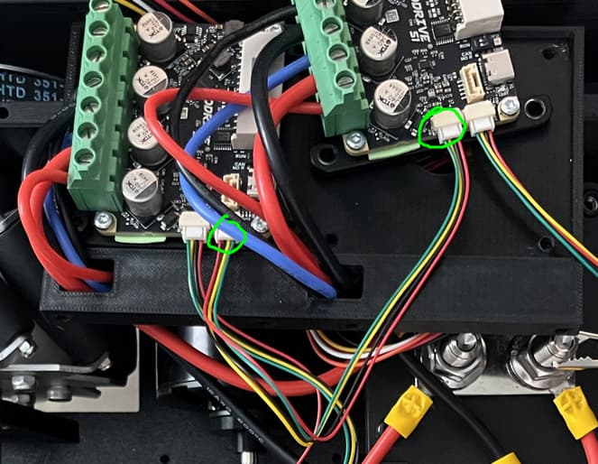
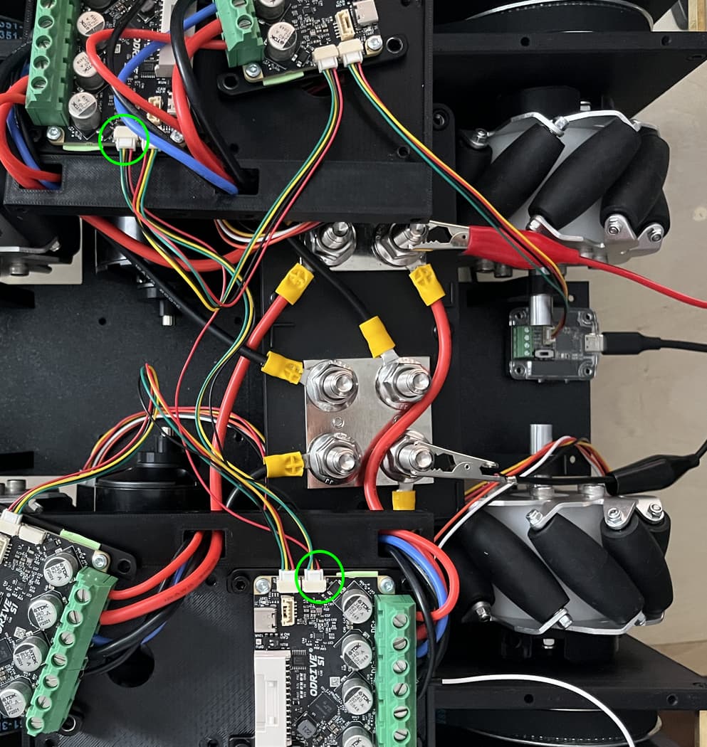
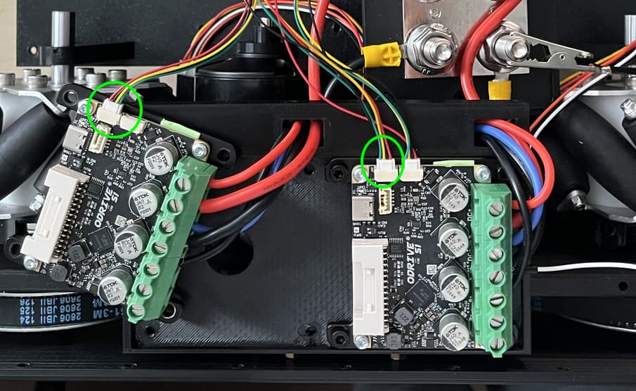
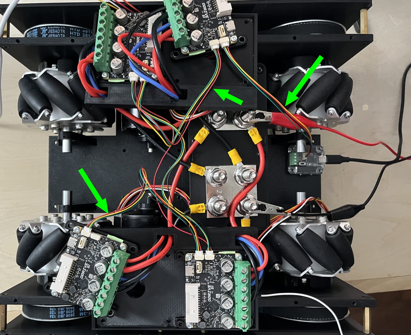
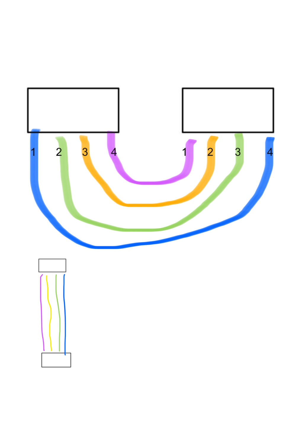
So this would 100% explain why only the second and third ODrive in the chain work – those are the only ones with the correct CAN wiring, the other two have CANH/CANL (as well as VBUS/GND, but that matters less in this configuration since you’re not externally powering the S1s over the CAN lines) swapped.

I’ve highlighted the CAN cables that have pinouts swapped, fix those and the whole setup should work!

Haha!

Of course that’s the solution! That’s what I get for ordering JST cables and forgetting about them instead of crimping my own.

It’s also funny that I looked into every other problem except looking at the actual wiring of the cables.

A quick recrimp (reversing the order of the cables on one side) was all I needed.

I have attached an image of the geometry of the plugs (1 maps to 4, 2 maps to 3, ect.) leading to the mismatch incase any others overlook this too.

Thanks again!

Great to hear that fixed it! It’d be lying to say if I haven’t made that same mistake before :slight_smile: