Hey everyone I am currently using CAN bus to control four ODrives via a Feather Can M4 Express from adafruit. I have a serial to CAN bus converter firmware written that allows me to connect to the CAN Bus via serial. I am using an oscilloscope to look at the waveform of the CAN bus data and found something interesting.
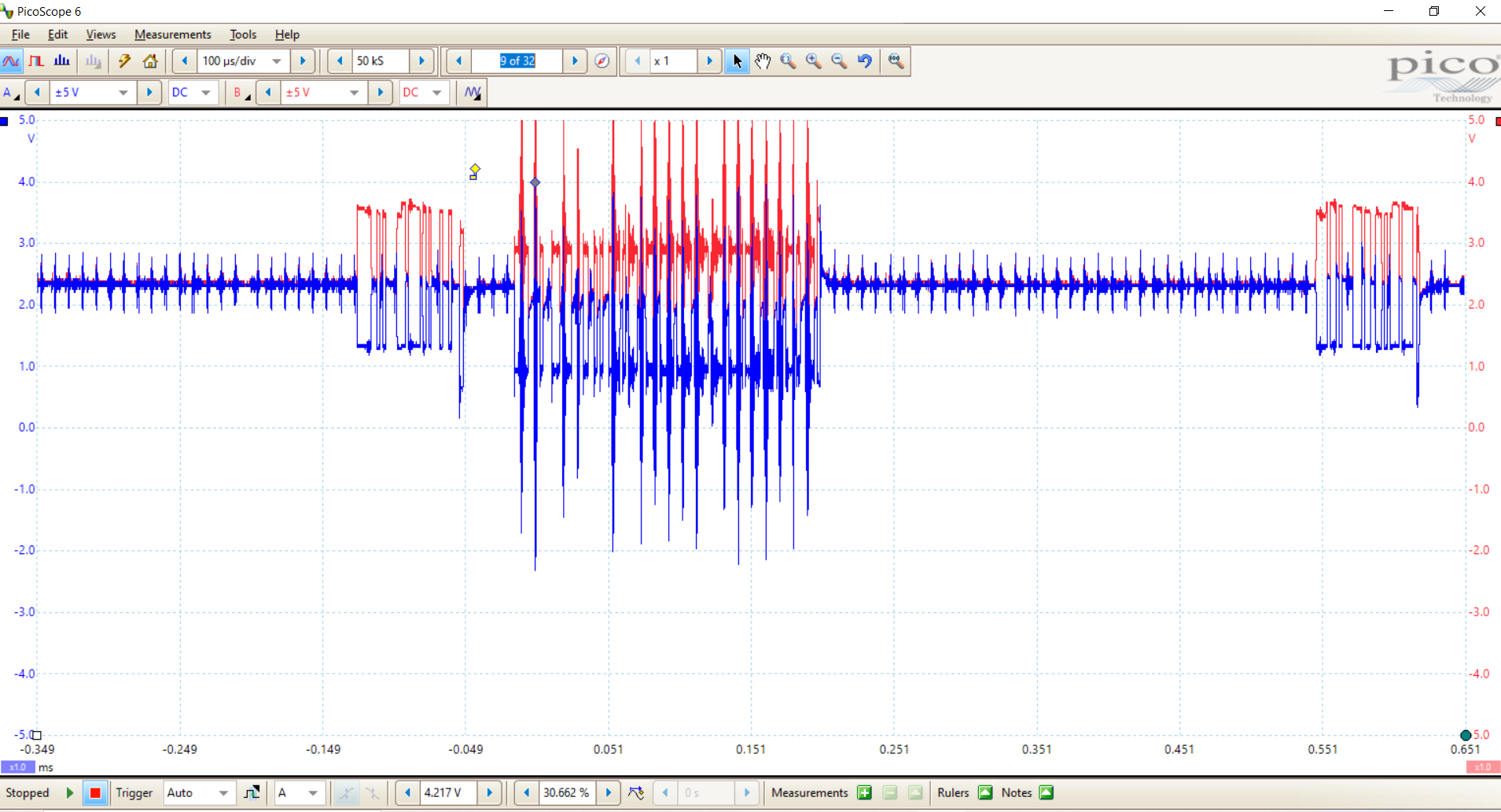
All the ODrives are powered via 52V. The first issue or concern is the general spikiness of the signal even with no data being sent via the CAN bus. The first block of signals being sent are requests for voltage data to be sent from all 8 ODrive devices. Then the following response is the voltage data being sent back from the ODrives to the Feather CAN. However, as you can see it is extremely spiky indicating a good deal coming from the Odrive.
I thought this may have been bus collisions so I then changed it to ask only one ODrive for voltage and I got the same result, a very noisy response. Granted it works great I am just curious if there is a way were could remedy this to try and produce a cleaner signal or if anyone else has had this issue.
Motor drivers are a noisy environment. CAN uses differential signaling exactly for the reason to be resiliant to this type of noise. Make sure you use twisted wires between the CAN_H and CAN_L signals.
After that, get your scope to show you the difference between the signals, and make sure you have a high bandwidth/sample rate on the scope. I hope it will show that the differential signal is clean, except for some noise picked up on the scope probes.
I am using twisted wires specifically for can bus and also adjusted my sample rate to 10us per division and still see a high degree of noise. The bigger issue is that this noise was present with no robots even running. Also, I had 120-ohm resistors on each side when testing, I also tried without the switch enabled and it looked the same which is interesting. I am using an Arduino Feather M4 CAN to convert serial to CAN bus data.
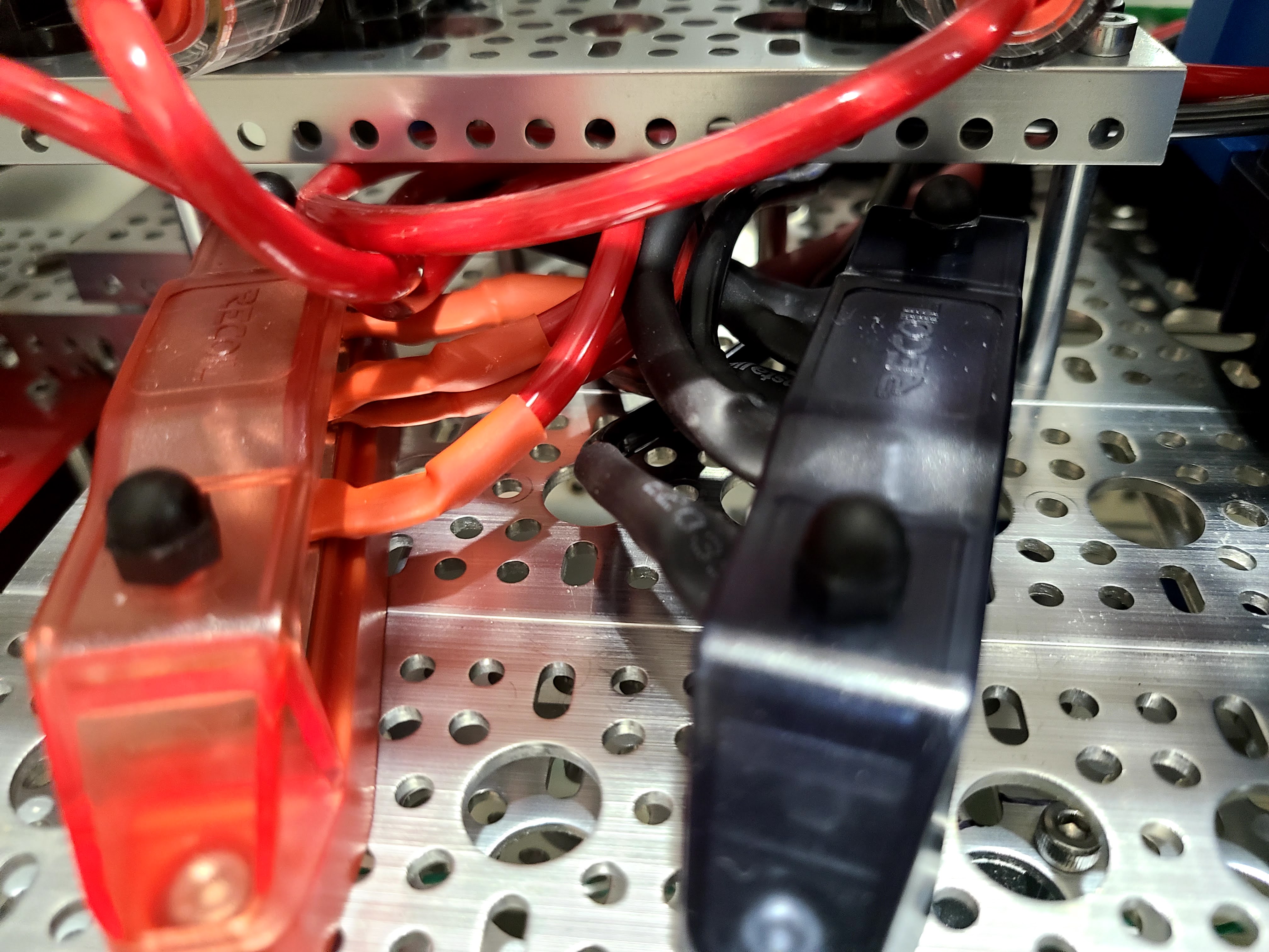
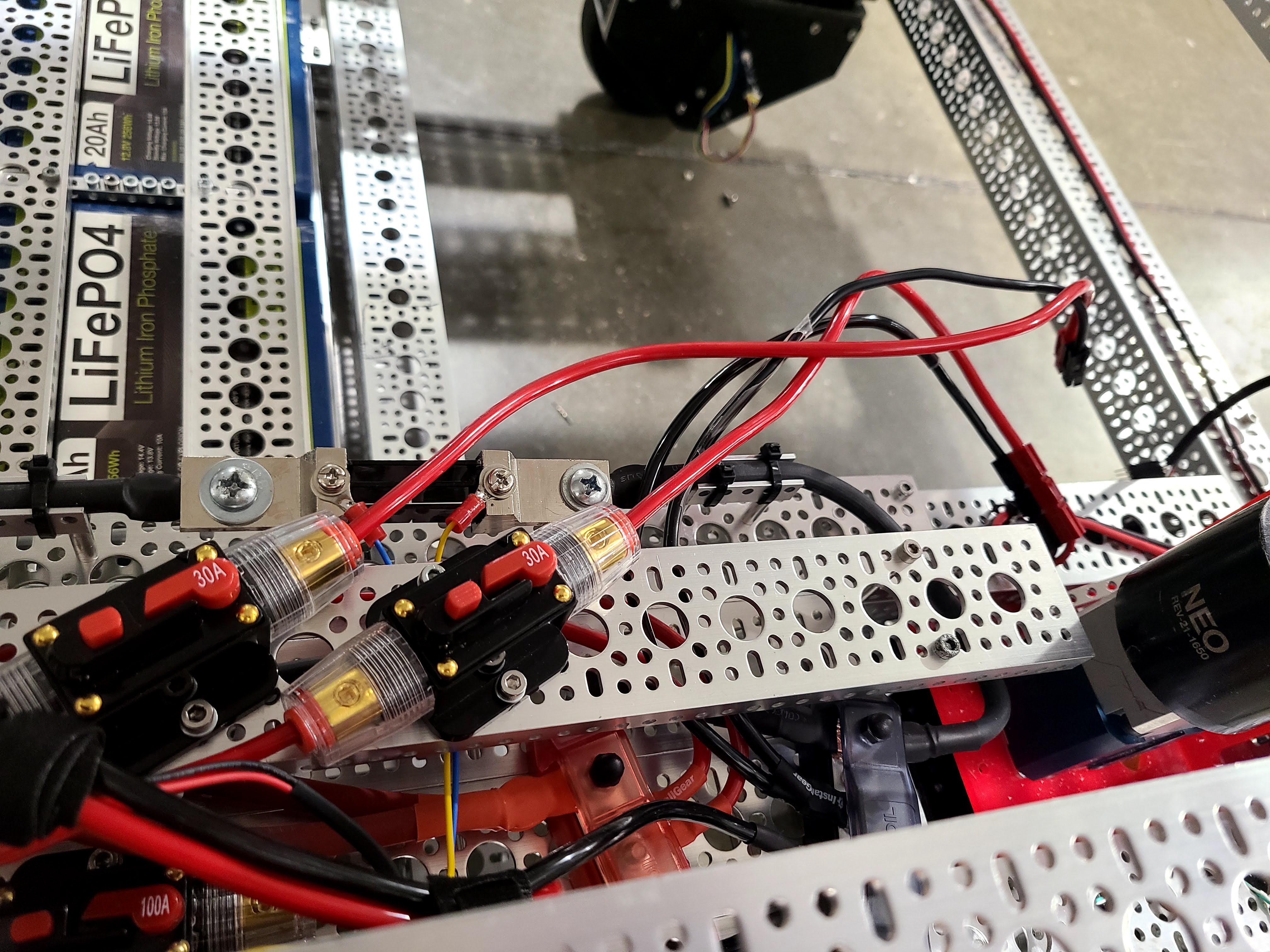
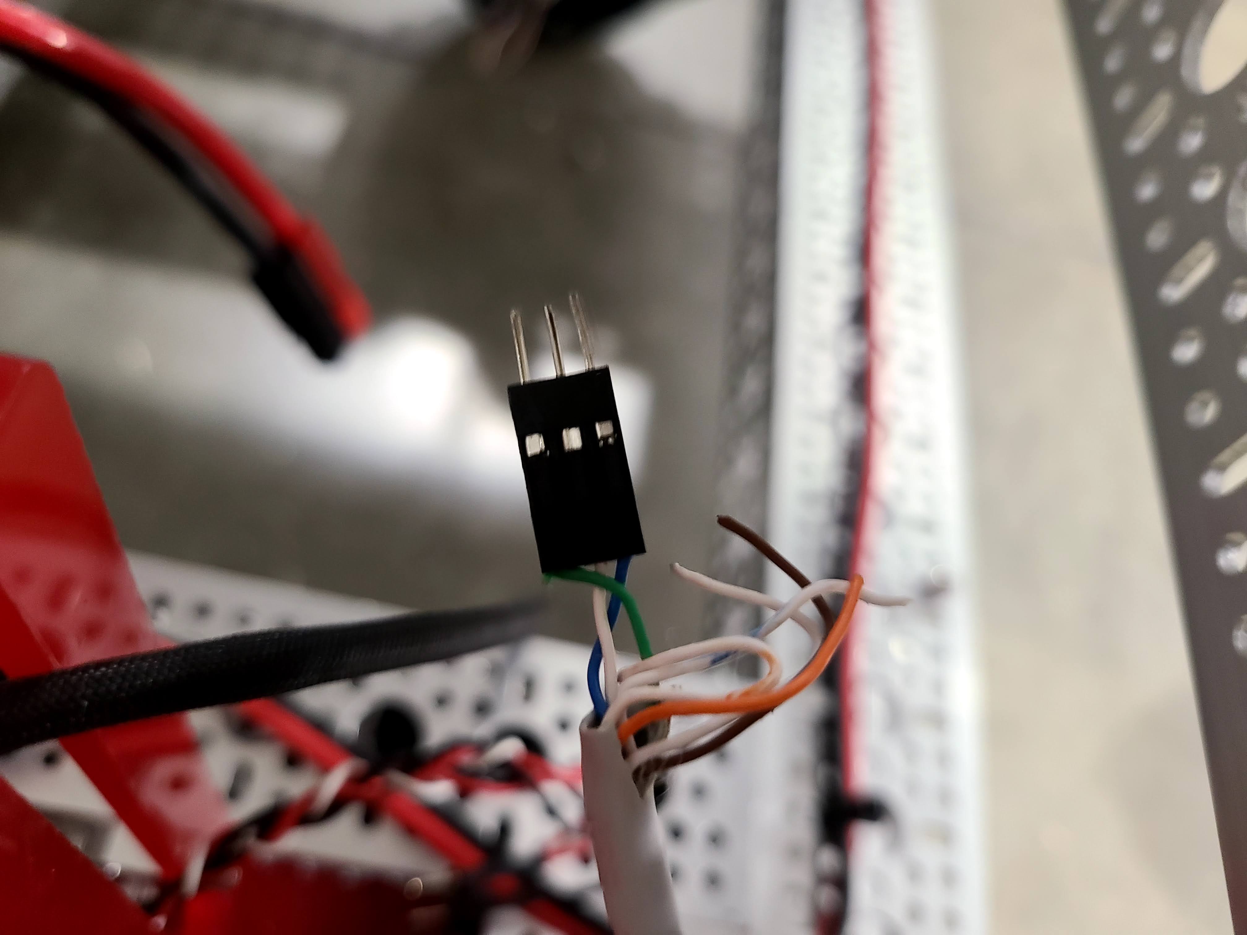
Today I was working on the can bus trying to reduce noise levels by slowing adding ODrives and seeing how it affects the noise on the scope. I have had 3 ODrives break on me in the past presumably too ground loops from connecting to it with serial while driving motors. Now today another 2 ODrives died on me, this time no serial was plugged in. I did have CAN bus plugged in as well as a ground cable from the Feather to the ODrive to ensure both are on the same ground. The feather was then plugged into my computer. I have been very careful with the wiring to ensure proper gauge wire is being used for the power and we are running at 48V. Once again I want to reiterate that no motors were even moving all I was doing was sending CAN messages asking for the vbus voltage. I have attached pictures of the wiring below. I love these boards but just cant seem to get through issues that are causing the boards to seemingly die. When I measure voltage on the broken boards I have full 5V but the 3.3V line is only at 0.5V and all the chips get extremely hot. Any Ideas?
Can you share your wiring schematic? You’re doing something that’s frying the STM chips. Considering you have some other source of noise in your system (CAN noise with no bots running?) I suspect power supplies or similar.
Dead (hot) STM32’s is usually caused by injected currents due to ground loops hitting the logic pins. Do you have a diagram of your logic wiring, and how various grounds are connected together?
@Wetmelon Regarding that, I am using the Odrive Pro and I want to use the CAN, however, I can’t find how to activate that internal resistance. Is there an internal resistance on that new model?
Have you found a solution ? VFD’s in general are notoriously noisy because of their nature.
CAN is extremly tolerant and in general you never have any problems until you do. It doesn’t mean it wasn’t there ! at 20khz switching. it is almost garanteed that every CAN message will intersect with a switching spike. If every nodes on the bus react exactly the same, the common mode switching will be ignored … BUT when the commutation under/over-shoot of multiple drive add-up, both inputs of a receiver node can end-up looking “lower then their local ground” → a “0” could be interpreted as a “1”.
How we solved it : one CAN isolator per VFD, all other non-switching nodes could live harmonously on the non-isolted side. Electricly speaking , there is only one transceiver talking to each VFDs and it’s gnd reference follows the bounciness of the VFD switching noise. A metric I used to gage the effect of such approach is CANerror cnt / 5 seconds. Before the isolators, I would have good systems at 8-9 errors per 5 seconds at the whole thing would start acting weird past 10-12 … Kinda like limbo dancing. no need to be the lowest , just don’t touch the bar !
After using one isolator per VFD, I would get <1 error per minutes. I don’t know if you have a commercial product of more of a personnal project. Can Isolators are not really cheap ( curtis 1360 are probably the cheapest ) but you can possibly use an isolated transceivers and use the “Second CAN ctrl” of your CAN m4 express : CANBus Unit(CA-IS3050G) | m5stack-store.
I’ve worked with CAN on commercial products for the last 15 years and only on the last 4 did I start to “SEE” the problem as most of my other work, I managed to limbo without touching the “Bar/Pole”.
On the bench, 1x ODrive + 1xPC nver fails … On a product with multiple drives with multiple CAN transceivers from multiple manufacturers with multiplle different “filtering” circuits induces resonnant frequencies that are extrmly hard to isolate.
Sometimes, you disconnect one drive and the problem no longer shows up and you start blaming THAT drive but you sometimes notice that it does the same with any drive you “Isolate”