@Wetmelon Thanks for the reply! By looking at another thread talking about the flashing the custom firmware, we realized that we didn’t flash the firmware. We successfully solved the issue by following the firmware developer guide.
Thanks!
@Wetmelon Thanks for the reply! By looking at another thread talking about the flashing the custom firmware, we realized that we didn’t flash the firmware. We successfully solved the issue by following the firmware developer guide.
Thanks!
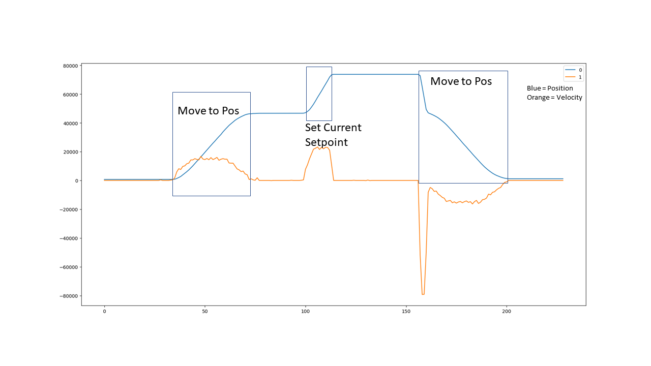
Hi @Wetmelon, It appears that the trapezoidal acceleration and velocity limits are disregarded when switching from current, or velocity, to position mode. As you can see on the plot below, the move to position command works nicely with the trapezoidal motion limits and when I send a current setpoint the motor winds up as expected. The funny thing is that if i send another move to position command, the trapezoidal acceleration and velocity limits wont kick in until its back to where it left off from the last position commanded. I understand this is not a usual application, but I thought it was worth the mention in case this behavior is unintended and you would like to apply a change. 
hi @turndog! Thanks for the detailed bug report.
This is expected behaviour. The trapezoidal planner uses the pos_setpoint and vel_setpoint as the starting position and velocity, as these are more stable when you stay in trapezoidal mode all the time and you have feasible trajectories. Current control mode doesn’t update pos_setpoint or vel_setpoint, so they retain their values from the point at which you changed to current control mode. To fix this, you can set pos_setpoint = pos_estimate and vel_setpoint = vel_estimate just prior to calling move_to_pos. I will also consider changing move_to_pos to use the measured values instead to eliminate this kind of behaviour.
Excellent, thank you for the explanation and the suggested fix.
Hi, Wetmelon, I’m very grateful for your contribution, it has greatly simplified my job. I have a small problem here, could you please tell me the difference between Current Setpoint and IQ Setpoint? Can the two parameters convert into each other?
In current mode they will be identical. In other modes they will be different values (unless I’m sending the wrong data)
Hi, Wetmelon, I’m building up a four-leg robot using Raspberry Pi 3 b+ with PiCan2 CAN bus transceiver. I’m wondering how can I control the Odrive with Odrivetool (python) via can-simple? The odrive boards are successfully flashed with the firmware contents from your branch. Are there any available examples we can reference to? Thanks a lot!
How is the compatibility with CANopen? would it be possible to use a CANopen module like Beckhoff EL6751 to interface odrives into an ethercat network and control them from there?
The CAN Interface is working great. Thanks!
But how can I change control mode (in my case to current control) via CAN?
I can set the state to closed loop control (CMD ID 0x007) and send current setpoints (0x00E). But that is only working if I change the control mode in odrivetool in between.
Isn’t there a CAN command for that?
0x00E should automatically set the control mode to current control first. If it’s not working, there might be something else wrong.
Try using the command “set_current_setpoint(float)” in odrivetool directly while you’re in a different control mode.
Hi,
I used this arduino shield to communicate with Odrive :https://www.aliexpress.com/item/32672184774.html?spm=a2g0s.9042311.0.0.27424c4dAJPHtm
This is my code :// demo: CAN-BUS Shield, send data
#include <mcp_can.h>
#include <SPI.h>
MCP_CAN CAN0(10); // Set CS to pin 10
void setup()
{
Serial.begin(115200);
// init can bus, baudrate: 500k
if(CAN0.begin(CAN_500KBPS) == CAN_OK) Serial.print(“can init ok!!\r\n”);
else Serial.print(“Can init fail!!\r\n”);
}
//unsigned char stmp[8] = {0x00, (0x40 >>8), (0x1c >> 16), (0x46 >> 24), 0x00, 0x00, 0x00, 0x00};
unsigned char stmp[8] = {0x00, (0x40>>8), (0x1c >> 16), (0x46 >> 24), 0, 0, 0, 0};
void loop()
{
// send data: id = 0x00, standrad flame, data len = 8, stmp: data buf
CAN0.sendMsgBuf( 0x6C, 0, 8, stmp);
delay(50000); // send data per 100ms
}
/*********************************************************************************************************
END FILE
*********************************************************************************************************/
In [54]: odrv0.can
Out[54]:
error = 0x0000 (int)
config:
baud_rate = 500000 (int)
can_protocol = 0 (int)
set_baud_rate(baudRate: int)
However nothing happens . no movement at all. can anyone help. Thank you.
BTW my library is from Coryflowler.
It probably doesn’t help that you are sending a frame of just zeroes.
You’re not using your bitshift operators properly.
(0x40 >> 8) == 0 (0x1c >> 16) == 0 (0x46 >> 24) == 0…
What are you trying to send? What movement are you expecting and why?
Hi ,Towen
I am trying to To set axis0 position to 100000
Like Odrivetool command:
odrv0.axis0.controller.pos_setpoint = 10000
Can you please teach me how to bitshift properly ? Thank you.
So, what part of your command expresses the "odrv0.axis0.controller.pos_setpoint = " part?
You are just trying (and failing) to send the number 10000, which makes no sense, unless the ODrive is set up to expect this, and treats all numbers recieved as position setpoints for axis 0.
As to bitshifting, you are doing it twice, I think. Once in your head, and a second time in the code. You don’t need to write each byte of the number you are trying to send.
So your bytes are:
(10000 & 0xFF)
((10000 >> 8) & 0xFF)
((10000 >> 16) & 0xFF)
((10000 >> 24) & 0xFF)
Tom
Hi Tom,
Sorry for the late reply . I was out of town.
To set axis0 position to 10000:
Axis ID = 0x03
Command ID = 0x00C
CAN Message ID: = 0x03 << 5 + 0x00C = 0x6C
@seatle OK, having RTFA above, I have got it working on my odrive
I am using axis1 with default CAN settings, RazorsEdge branch. Node ID is 63 (0x3f), apparently, which translates to 0x7e when shifted left by 5 bits.
In [72]: odrv0.can
Out[72]:
error = 0x0000 (int)
config:
  baud_rate = 250000 (int)
can_protocol = 0 (int)
set_baud_rate(baudRate: int)
In [73]: odrv0.axis1.config.can_node_id
Out[73]: 63
I am using a raspberry pi with “skpang” CAN hat. I have installed the can-utils package to easily send CAN frames from the command line.
First, I set up the CAN interface like so:
pi@rpi:~ $ sudo ip link set dev can0 down
pi@rpi:~ $ sudo ip link set dev can0 type can bitrate 250000
pi@rpi:~ $ sudo ip link set dev can0 up
Then I run candump can0 - I can see heartbeat messages from each axis:
  can0  001   [8]  00 00 00 00 01 00 00 00
  can0  7E1   [8]  00 00 00 00 08 00 00 00
  can0  001   [8]  00 00 00 00 01 00 00 00
  can0  7E1   [8]  00 00 00 00 08 00 00 00
  can0  001   [8]  00 00 00 00 01 00 00 00
So it works! 
But I can’t see any messages because of the spam…
In odrivetool I set the heartbeat rate to be 10000 ms (10s) to avoid spamming my terminal:
In [70]: odrv0.axis1.config.can_heartbeat_rate_ms=10000
In [71]: odrv0.axis0.config.can_heartbeat_rate_ms=10000
Let’s say I want to query the DC-bus voltage.
I use Ruby (IRB) to calculate my message in hex, knowing that my node-ID is 63(dec) and the “get DC Bus” is 0x17 (hex):
irb(main):014:0> ((63 << 5) + 0x17).to_s(16)
=> "7f7"
So, leaving candump running in another terminal, I run cansend to query the DC-Bus voltage, like so:
pi@rpi:~ $ cansend can0 7f7#RIn the first terminal I look for my message and response:
  can0  7F7   [0]  remote request
  can0  7F7   [8]  33 F5 42 41 00 00 00 00
Nice, I have a response. But it’s encoded as a float. So I’ll again use Ruby to decode it…
irb(main):022:0> "\x33\xF5\x42\x41".unpack("f")
=> [12.184863090515137]
12.1848 volts. Looks about right.
Now here’s the bit maybe you didn’t do, I send the axis enable command:
pi@rpi:~ $ cansend can0 7e7#088 being the value of AXIS_STATE_CLOSED_LOOP_CONTROL
I hear the motor start and it is now holding position at zero. Success!
Now, I can try sending a position command:
irb(main):023:0> ((63 << 5) + 0x0B).to_s(16)
=> "7eb"
pi@rpi:~ $ cansend can0 7eb#00
pi@rpi:~ $ cansend can0 7eb#08
pi@rpi:~ $ cansend can0 7eb#ff
pi@rpi:~ $ cansend can0 7eb#ff.ffNothing happens… I go back to odrivetool.
In [75]: odrv0.axis1.controller.input_pos
Out[75]: 0.0
In [76]: odrv0.axis1.controller.input_pos=100
In [77]: odrv0.axis1.controller.input_pos=1000
Still nothing. Turns out this was because input_mode was not set (should have been saved from my config, but maybe it didn’t…?)
In [80]: odrv0.axis1.controller.config.input_mode
Out[80]: 0
In [81]: INPUT_MODE_PASSTHROUGH
Out[81]: 1
In [82]: odrv0.axis1.controller.config.input_mode=1
Now, it sort of seems to work, but the motor only twitches slightly… I tried different values and it eventually shuts off completely.
It turns out I was sending the wrong command. The command values used by RazorsEdge have changed since the top post in this thread.
RTFS here: https://github.com/Wetmelon/ODrive/blob/RazorsEdge/Firmware/communication/can_simple.hpp
Counting down the enum, it seems I should be sending command number 12, not 11. Move_to_pos is replaced by set_controller_modes, which explains why I was getting confused earlier.
Now it works.
MSG_SET_INPUT_POS is command ID 12, and has three parameters:
Position (int32, little endian)
Velocity feedforward (int16, little endian)
Torque feedforward (int16, little endian)
I can leave the feedforward terms as zero, and just set the input_pos:
irb(main):026:0> ((63 << 5) + 0x0C).to_s(16)
=> "7ec"
irb(main):031:0> [1000,0,0].pack("l<s<s<")
=> "\xE8\x03\x00\x00\x00\x00\x00\x00"
pi@rpi:~ $ cansend can0 7ec#e8.03.00.00.00.00.00.00
pi@rpi:~ $ cansend can0 7ec#00.00.00.00.00.00.00.00The motor moves to position 1000, and back again. 
So, for your C code on the arduino, I’d probably do something like this:
#define CMD_SET_INPUT_POS 12
void setInputPos(uint16_t axis_node_id, int32_t pos, int16_t vff = 0, int16_t tff = 0)
{
    uint64_t data = pos + (vff << 32) + (tff << 48);
    CAN0.sendMsgBuf((axis_node_id << 5) | CMD_SET_INPUT_POS, (unsigned char*)(&data));
}

...
uint8 my_axis_id = 0x03;
setInputPos(my_axis_id, 1000);
Just to check my bitshift operators, again Ruby’s array:pack comes in really handy 
irb(main):038:0> [1000 + (1 << 32) + (1 << 48)].pack("Q<")
=> "\xE8\x03\x00\x00\x01\x00\x01\x00"

irb(main):041:0> [1000 + (1 << 32) + (1 << 48)].pack("Q<").unpack("l<s<s<")
=> [1000, 1, 1]Yeah, sorry - RazorsEdge commands don’t quite match the CAN branch commands due to the changes introduced by the input_filter branch.
I believe the protocol documentation on the RazorsEdge branch is up to date, however https://github.com/Wetmelon/ODrive/blob/RazorsEdge/docs/can-protocol.md
Hey Wetmelon, thanks for all the work on implementing CAN for Odrive!
I was reading through this entire post, some of the PR’s on your fork, and the PR you have on the main Repo. What is the general plan for getting your CAN work in the master repository? Is there a list of things that need to be fixed, validated, and tested?
I was wondering because after reading this thread, it seems like a lot of people have not had an easy getting a test setup for CAN. I have done quite a bit of work with a PCIe PCAN card using SocketCAN, but was thinking about developing a quick STM32 and SN65HVD242D board or maybe an existing board/shield combo. Do you think it is worth developing something new or using something existing? Either way, I would like to set that up and create a pretty decent write-up so that we can get more people using CAN without a lot of troubleshooting on a bunch of different setups. What are you thoughts?