I was just about to buy an oDrive Pro, but after checking the pinout page in documentation, it’s not as obvious how to connect two Hoverboard motors and their hall-sensors (the v3.6 board is very clear in its connections pinouts).
Am I right in thinking the Pro board only runs one motor? Is there any documentation that shows how that motor’s three power cables and five sensor cables should be connected?
I was only going to upgrade from my v3.6 to avoid doing the capacitor soldering mod on the hall-inputs (which overcomes a noise error). Is it worth upgrading, buying two Pro boards? Will it be more complicated to control two Hoverboard motors from Arduino/oDrive than if I stick with the v3.6?
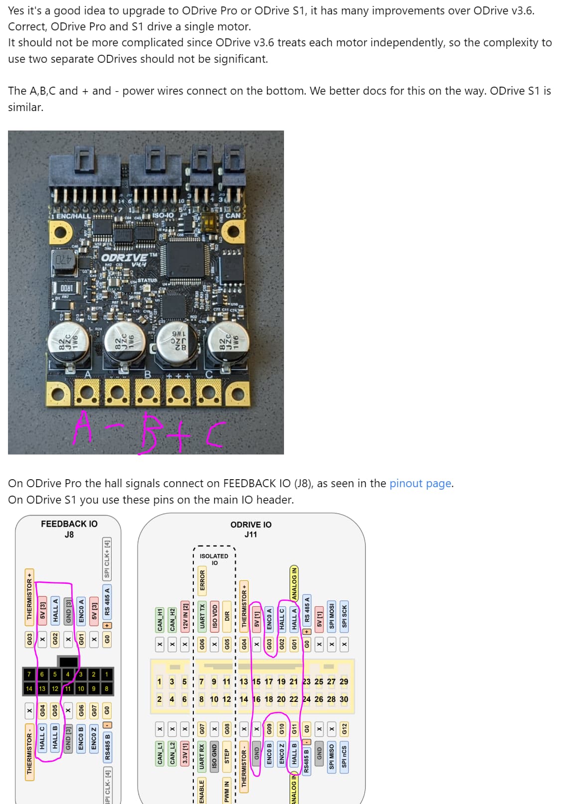
But simply solder the phase (power) wires to the pads labeled A/B/C, and then assemble a connector to connect the power/ground of the hall sensors to 5V / GND, and then connect the U/V/W wires to the pins labeled Hall A/B/C. Done!
Is it worth upgrading, buying two Pro boards?
You may want to consider waiting for the S1, which is planned to open up for sale on the site by Wednesday. It’s also only single axis, but it’s less expensive than the Pro because it’s lower power and has fewer features overall. For a home hobby project it’s perfect.