No dramas, thank you for watching, I tried to put as much info into them as I could to show setup from a new user perspective.
Ok I bought Tarot 4108 laat week and just now the Odrive. I’m still puzzling on the power supply a bit as there are so many options though. But at least now I understand what can be used in order not to blow up batteries and Odrives 
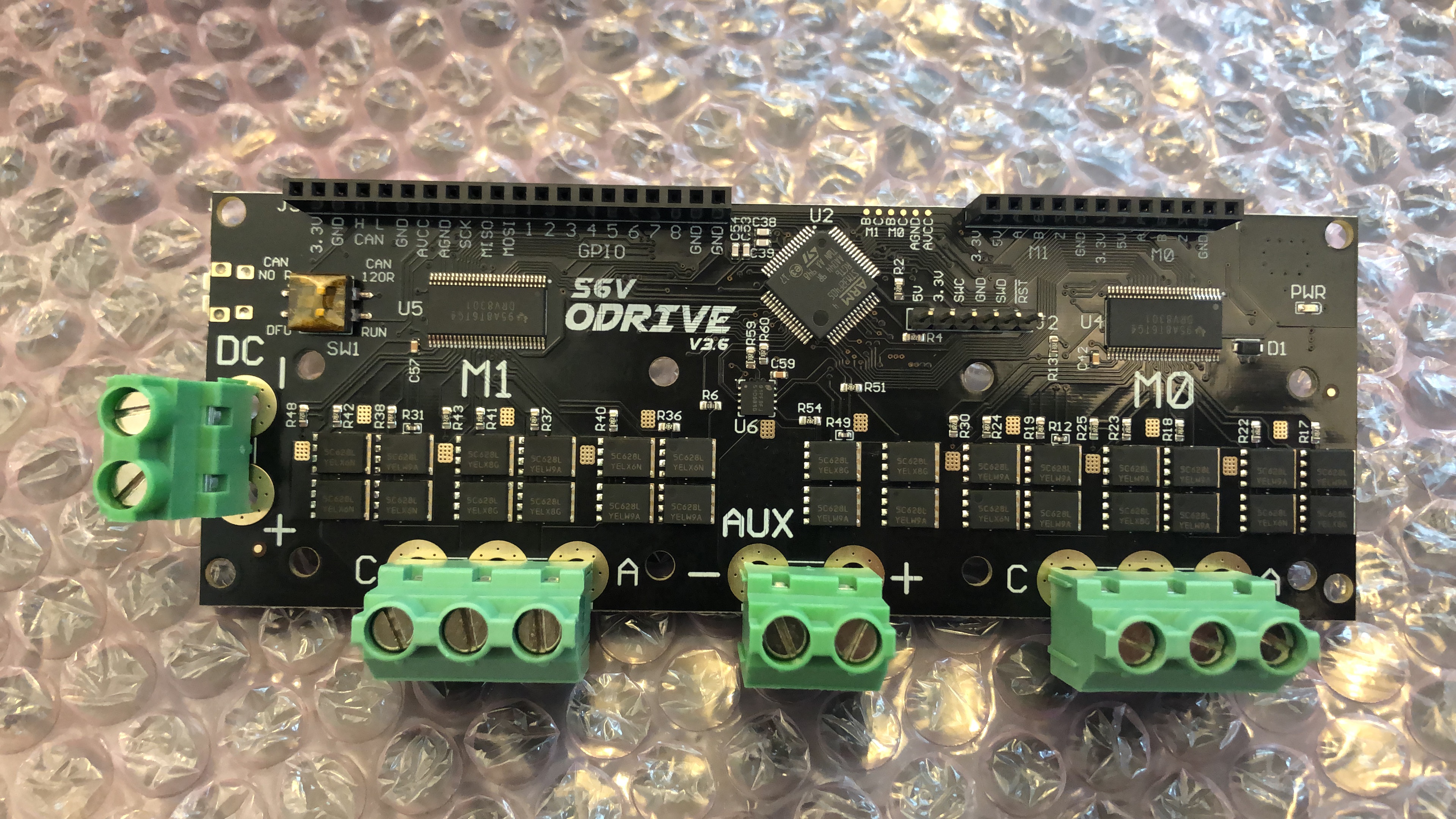
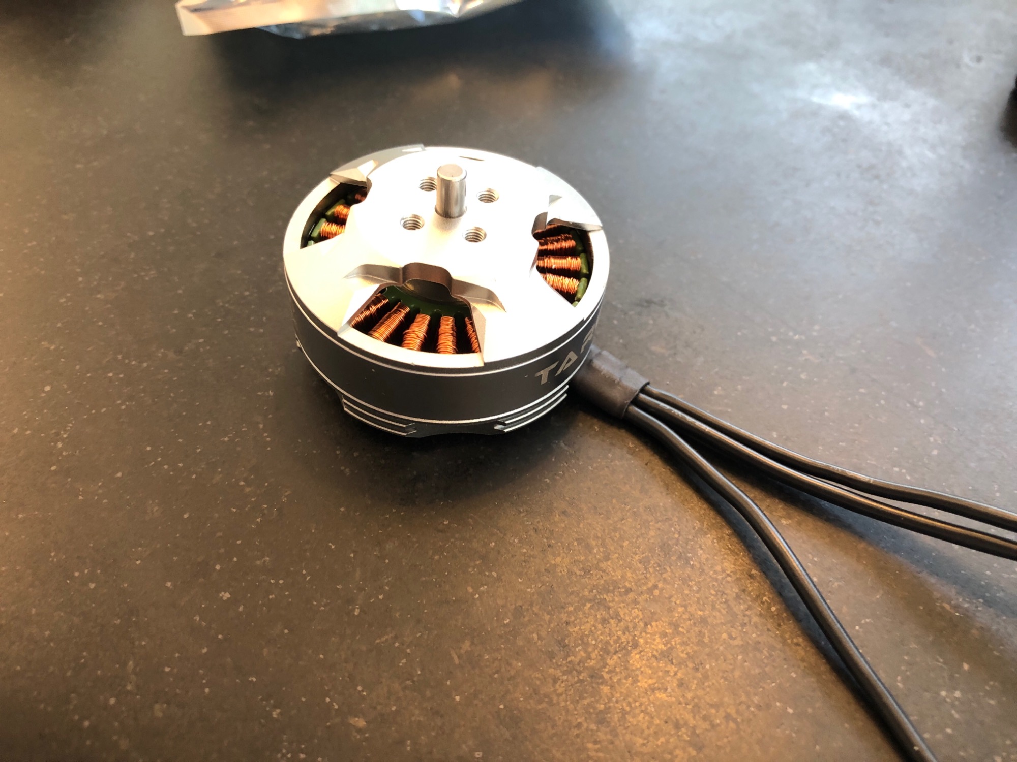
Stuff is arriving…  .
.
Still figured what encoder to buy. To be honest I would like it best to place it on the pulley then on motor at some point as discussed elsewhere on the forum.
I recogn I’d have about 10 to 15 rotations a sec maximum. It is normal to zero 3D printers, so that would be fine for me.
Thans for the advice!
Encoder on a pulley is a bad idea. If the belt slips over time your machine will go out of position, lose torque, and eventually the drive will fail to commutate the motor. You could also get into a really nasty dynamic oscillation if sudden acceleration of the motor causes the belt to stretch, even by a tiny bit.
Can’t you mount something like an AS5047p to the back of the motor?
I will start with encoder on the shaft die sure. Yet in the end I’d like to put it on the pulley. Gate belts don’t slip with they teeth and all and are (relatively) stiff. I computed first resonance frequency of the setup in the order of 120Hz. Should be possible to get a stable feedback on it would be my guess abs in the other thread I read the motor and pulley could get out of sync multiple degrees so feels like possible in principle? But you are right, I should start with the basics!
What is the best way to glue (?) a magnet on the rear end shaft of the motor? And how important is alignment of the magnet on the center of the shaft for encoder performance?
In my experience, the alignment of the magnet is not very important at all! The sensors are extremely tolerant of a magnet that has been superglued on the piss, or a sensor that is mounted slightly off axis.
Superglue tends to work well for me, because I can remove it if necessary. Maybe for speeds of 10krpm+ you might want to be more careful, but only to avoid the magnet pinging off.
1 Like
Thanks Towen, I really appreciate your patience with me and great suggestions and help.!
Hope to receive a Pi this week so I can start!
1 Like
Weird, in my experience a fraction of a mm causes a complete failure of the encoder data 
Interesting… What failure do you get? I’ve recently had SPI COM errors due to a fault flag from the encoder, but that seems entirely unrelated to motion ie it measures perfectly when I turn the motor by hand, but recently when I turn the motors on, I get the SPI error until I power cycle the encoder itself. Previously they all worked fine. Probably i need to tie MOSI to 3v3.
One motor even has just a 3mm magnet shoved inside a rubber grommet, with the AMS board on a couple of nylon standoffs. No issue with measurement at all.
I was getting all sorts of nonsense, but maybe I should revisit it since I’ve since discovered my setup doesn’t work unless I configure the software just so
I’m about to buy a power supply for the motors but wonder if say a Meanwell 240W supply in 24V or 48V for the Tarot 4108? And is 240W to dunne just the two motors enough (motors have to pull max 600gr each without a gearbox and a pulley that does 35mm belt motion on one revolution?
I also do hard to find the AS5047P here in The Netherlands… And while reading I had the impression it “only” gives 4096 pulses per rev?
@Quintin_Brand Can’t you get Mouser in dutch land? 
https://eu.mouser.com/ProductDetail/ams/AS5047P-TS_EK_AB?qs=Rt6VE0PE%2FOfJKFTMKo%2BL0Q==
It gives 16384cpr in SPI mode. Its default setting I believe is to send only 4096cpr over the incremental A/B/I interface, but it is possible to change that with some SPI configuration commands (you’d need to write your own code to do this, not something ODrive supports - i’d recommend just use SPI directly as an absolute encoder)
240W is plenty for full torque, but not enough for both full torque and full speed at the same time, (which you probably don’t need).
I’d go with the 48V PSU and the 56V ODrive always - it’s better to have the voltage headroom for control performance, even if you don’t need the max speed at 48V.
THX Towen, I’ll order the 48V now as indeed I don’t need full speed (at all). Max 1rev/sec gives 35mm travel and by the time I hit 300mm/s my hotend and / or extruder won’t keep up anymore.
As for the encoder, thx! As I’m new to encoders: the 16k pulses over the 4k is because in SPI mode it also counts the falling edges although the encoder itself “only” has 4k rising edges on A and B? Or is the 16k an interpolation and no real unproven in accuracy?
I think that if it’s going to work on my printer it’s due to the encoder precision; speed is granted for sure with the Odrive setup .
It seems a duet WiFi is a nice 3D printing controller that has dedicated Step/dir output. Unfortunately I bought a Duet3, which is even nicer but doesn’t support Step/Dir output. In the latter case I would only be able to connect to the stepper driver output, where I loose the Step Dir info and I didn’t find some (analog) way to convert that back. It would be really cool though as the stepper drivers can output up to 100k “stepping pulses” per ref. So now than enough for the step dir input on the Odrive.
Would be cool if someone had an idea as I think it would be the “easiest” way for any 3D dude to hook up an Odrive… 
AFAIK there’s no interpolation going on, but there is a fair amount of noise in the lower bits of the sensor output. The default resolution of the A/B/I output is deliberately set lower than the internal resolution, to avoid sending out lots of pulses that are actually due to noise rather than real movement.
Using the full 16k counts on SPI still makes sense though, because you can average out the samples to get rid of the noise, to get the full resolution at low speeds.
Gah. 
There must be a 3D printer controller that supports something better than this. I know @Dev255 was able to use the ASCII protocol over serial from his Arduino for his CNC project, for example.
Can you find an open source 3D printer controller for Arduino and mod it to talk over serial or CAN bus? It would be so much better than step/dirt.
You can always try to modify Klipper to work with odrive. It’s wonderfully expandable if you can work with its timing scheme.
I am also interested in using Odrives with a 3d printer, i currently use Klipper, but i would like to add some servo motors as i cant achieve the acceleration i want with steppers. however i would like to use both servo’s and steppers with synchronized motion together. Klipper with Odrives seems like an combination for this
Just an quick overview of Klipper as i understand it, in case anyone is not aware:
Klipper does all motion planning on the Rpi ( or a more powerful PC) it then sends commands to a the MCU over USB or serial ( or possibly CAN?) and the MCU does the Step generation and general IO stuff.
Klipper supports multiple MCU’s and synchronizes them together if large numbers of steppers need to be driven with Tool changing printers etc.
https://www.klipper3d.org/Protocol.html.
now while STEP / DIR from an MCU to an Odrive should/could work fine for testing, i think a much better method would be to either modify the odrive firmware to support Klippers communication protocol, command Que and clock sync directly, or write a python module for klipper that can talk to the odrives using the existing odrive protocols.
Purely a guess, i haven’t dug around in to klippers code yet, but the second option is probably easier and more flexible. Should be more simple to receive odrive data back in to klipper too.
i will order an odrive and can dabble with some code soon. - does anyone have any experience with synchronized motion planning stuff, and could advise on what id need to look out for? - i hope that i could just extract position, acceleration and some kind of clock from klipper and send it to an odrive.
Hi bundle,
Thanks for adding to the discussion! I agree with both you and also with Towen who makes the same suggestion multiple times already.
Here my thoughts having experience with dynamic analyzers;
- a 3D controller is very helpful to start with: handling Gcode from standard Sliders, additional IO for heaters, Z probes etc. Not something you’d want to start implementing in Odrive SW.
- a decent 32bit speedy 3D controller completes more than enough Step/Dir commands for its own drivers. Motion planning is done in all 3D controllers (marlin, rap rap, klipper). So I think an Odrive in position mode would work in principle. I have to say it is still very unclear how the second order filter on the step/dir odrive input works though, but this should help for show moves for sure.
So I think we get down to the question on the latency really, because if the Odrive would do its own motion planing, extrusion and XY motion might just not match in principle (e.g. The 3D controller might compute a different way of moving and the corresponding filement extrusion doesn’t match.
Latency… Hmm, how much time did a stepper driver need compared to Odrive? Of its about the same, well then it should be OK!
My duet3 would be able to do CAN-FD, not CAN. But actually faster. Could work, but again depends on latency and I would still prefer instant Strp/dir style to make sure the Odrive acceleration etc is the same as the 3D controller wants. But if it aligns better in time, then it would be nice.
I think klipper is really set to work well with different hw simultaneously. It says it does synchronous operation, but no explanation on how it syncs. It would either have to measure outputs to determine latency or really clock the slave MCUs. I might be missing something but in general such masters slave operation on the same clock is not trivial. With the fast amount of hardware supportef I do hard to imagine true synchronous operation. I suspect all commands are send simultaneous to all slave devices. Their latency is then hopefully all about the same?
All in all I’d like to find a solution that requires minimal programming effort though: I’m not good at that.
I’m completely open to use marlin, rap rap or klipper though… And all of those have one thing in common: Step / Dir commands to their Stepper Drivers 
If you go to the developers section on the klipper documentation it explains pretty well how the timing works. It basically calculates the needed step times from the g-code, generates mcu commads with the timing scheme and then schedules the commands in the mcus queue. The MCU executes the commands according to its internal timers.
There’s no real need to sync the different controllers since time is the same for everyone and the paths are calculated beforehand.
Its just a bit funny to put an 8 bit mcu infront of a 32bit arm processor just to generate step pulses for its step/dir interface. A simpler solution would be nice.
Were going a bit off topic now. 
Off topic, I don’t think so: this is an essential part to make the Odrive work on a 3D printer.
One technicality concerning your (nice! and clear) explanation: I guess this means that the devices are not really in sync but because the Pi sends out “smaller” intervals each time, it would reset any accumulating time delay between MCU clocks (they never really run at the same speed) each time a new block is sent. So perhaps not sample synchronous yet only very small differences that are always reset so still good even after days of printing.
This would also work on a Duet I guess if I could connect the CANbus of the Duet3 to the Odrive. Only technicality there is that the Duet has CAN-FD whereas the Odrive has normal CAN. Have to check if that can work and I guess it would mean there might be a small delay between the execution of the Odrive and the stepper drivers on the Duet itself which is probably also negligible.
Well, interesting all of this stuff; today I ordered the encoders so hope to start trying some stuff soon.
CAN-FD is compatible with standard CAN.  There is no added delay.
Best idea would be to modify the Duet source to send out CAN position messages that the ODrive understands, instead of trying to make the ODrive understand the Duet’s native protocol (which might use FD frames that ODrive can’t recieve)