I was driving some hoverboard wheels yesterday with an odrive 3.6 and the wheel shaft (so the hub motor) was slipping without me realising which after a while lead to a smokey smell and the odrive disconnecting from the computer.
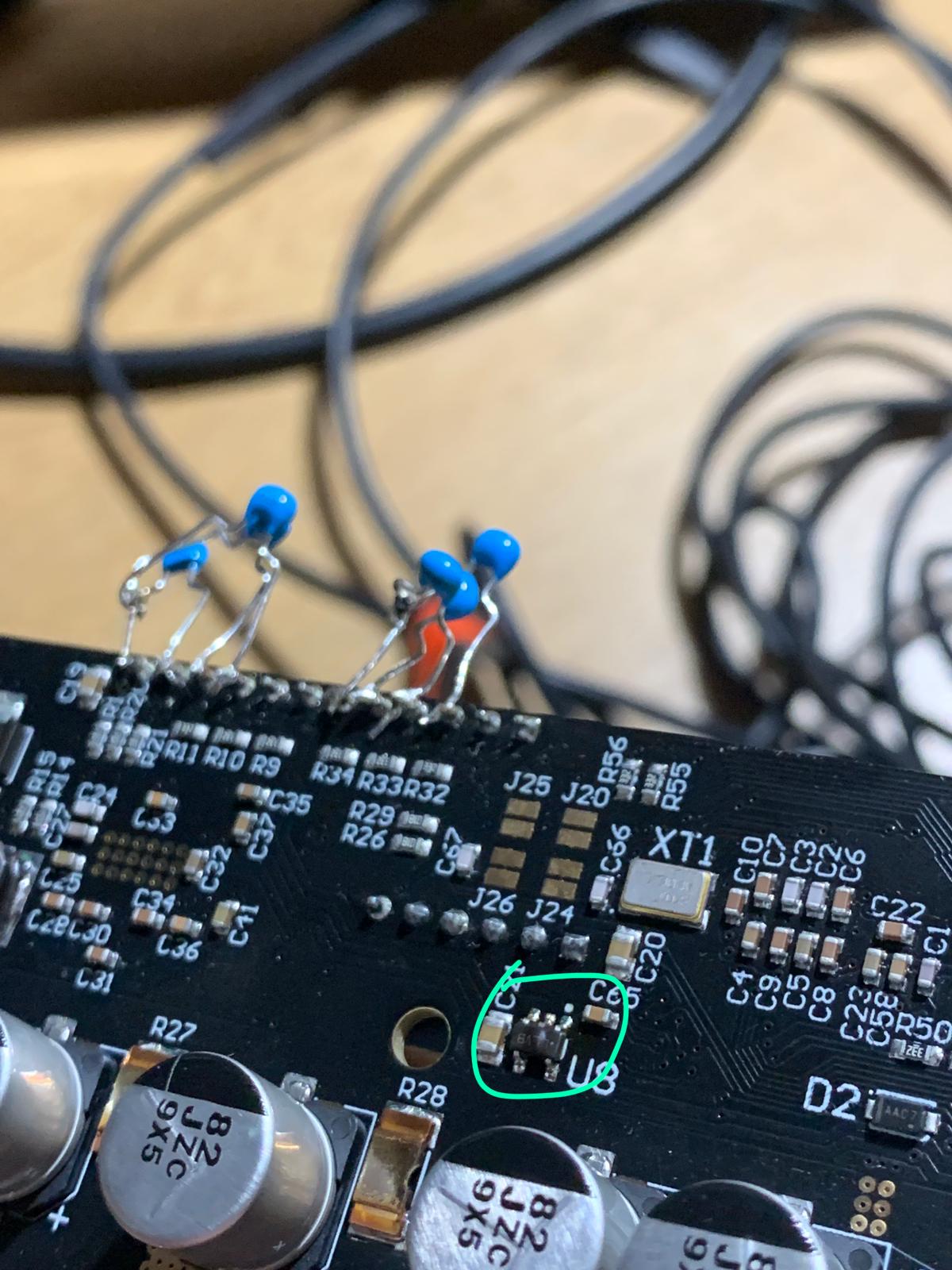
Upon inspection of the board I can only see U8 as slightly damaged and the board no longer connects to the computer.
What is this component and can it be replaced? What caused it to get fried? Was it the hall sensors? Do you think the board might work if I replace the component or should I check for other things as well.
Hmm. That’s the 3.3V LDO regulator for the analogue supply. Did you connect anything to AVCC?
Given that it doesn’t connect to USB though, that’s worrying (as it shouldn’t need AVCC for USB to work) - possibly you shorted VBUS to 5V, and have blown up everything on the 5V rail (including U8).
I’m not sure how a slipping shaft should cause any damage to the drive…?
So the motor started chewing up its own wiring?
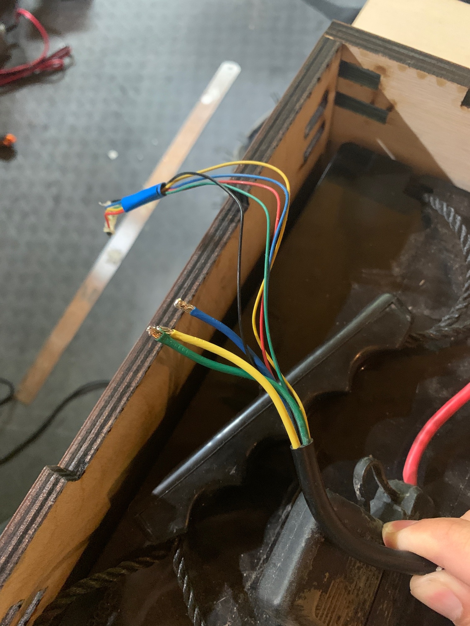
Is it possible that one of the encoder wires and one of the motor phases became shorted together during this incident?
Unfortunately, that could have blown most of the components on the board. i.e. the microcontroller, both gate drives, and the 3V regulators.
In future, I’d suggest that either your encoder wires or your motor wires (or ideally both) are shielded, with the shield connected to GND. That way, any shorts will go to GND before they touch any sensitive signals. It also helps a lot with noise, obviously. Also if possible route the encoder wires separately to the motor wires.
I appreciate that not all of us (including me!) have an easy way of doing this though…
According to the V3.4 BOM (latest published) it is LP5907MFX-3.3
Do you have the green power LED? If so then (at least one of) the DRV8301 gate drives is functioning, at least in its capacity as a 5V regulator.
Next to check would be to see if you have 3.3V on the 3.3V pins (so the other 3.3V reg is working)
Then if you have a scope, check for a clock signal on the MCU’s crystal oscillator.
If all of those are present, you could try replacing the LP5907.
It’s probable though that if you have the green 5V LED and 3.3V, but no USB, then the MCU is toast.
I’d buy a STM32F405RGT6 as well, just in case. (assuming you have an STlink or Nucleo board that you can program it with)
Yes that might have happened as the motor started spinning its own wiring for a couple of turns and maybe caused a short somewhere. However, I tried to run the motor with another odrive I have and it seems to work fine in closed loop control? So don’t know if there actually is a short. I could maybe try open the motor to check? (Sorry for all these questions which you probably are as clueless as I am)
My motor wires comes all in a single bundle without shielding…so not much I can do.
It could have been just a very brief short. Now that you have straightened the wires out, it won’t be shorted anymore. Have a look if any of the insulation is damaged. Or try twisting the wire near the motor with your multimeter on continuity test “beep”, with one probe connected to all the encoder wires, and the other probe connected to all the motor wires, and see if it shorts again momentarily.
Yes, your motor has the same wiring as mine. Not much we can do about it!
If you’re concerned about the same incident happening in future though, you could protect the encoder inputs (5V, A,B,Z) with zener diodes to ground and 100R series resistors. The zeners would conduct any voltage above 5V and so protect the chip, and the resistors would limit the current in the wires.
You could try putting your multimeter into Frequency mode if it has it, and see if you can read 8MHz across the crystal. This isn’t fool-proof though, because the presence of the meter could upset the oscillator and stop it working.
Have you tried putting the board into DFU mode with the switch and see if it shows up?
If you have a Linux computer or rasberry pi, check the output of dmesg -w when you turn on the ODrive. It might give a useful error message from the Linux kernel if the USB device shows up at all.
I put it into DFU now and it still doesn’t show up with lsusb and don’t think it appears with dmesg -w either (ran it as soon as I plugged in and don’t seem to find anything in the terminal - https://codeshare.io/21jAB1).