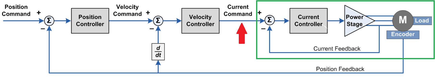
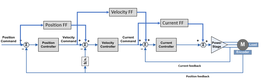
I am working on a project in which I want to use State Feedback Control to position control a BLDC motor in combination with the Odrive. I want to do this since translating time domain specifications into controller gain using this method is way more exact then the heuristic method of PID tuning. I would run the current control PD on the Odrive and the state feedback on a micro controller. For this to work a state space representation needs to be made of the the whole BLDC system. Using the control scheme from the Odrive Documentation (seen below), I wanted to determine the state space representation of the green box, where the current command is the input, as shown by the red arrow, and the motor position is the ouput. I have done much research and have found complicated versions which will require also modeling the inverter, or simple 2nd/3rd order systems .
My questions are:
What is the correct state space model to use?
Would you advise to take the other approach of applying system identification methods to determine the state space?
Furthermore, out of curiosity, what are the units of the command generated by the current controller? Is it voltage?
I assume that you are referring to the automatic identification of motor parameters (Inductance, Resistance). However from documentation, I thought that this was only used internally by the drive.
The main advantage of using the state space method is that the time domain requirements can be directly translated into controller gains, opposed to heuristic tuning of PID parameters to fit the time domain requirements, which is currently implemented in the Odrive.
That’s how the position and velocity control loops are currently tuned. The current control loop is tuned via pole placement, given a desired control bandwidth.
// @brief Tune the current controller based on phase resistance and inductance
// This should be invoked whenever one of these values changes.
// TODO: allow update on user-request or update automatically via hooks
void Motor::update_current_controller_gains() {
    // Calculate current control gains
    current_control_.p_gain = config_.current_control_bandwidth * config_.phase_inductance;
    float plant_pole = config_.phase_resistance / config_.phase_inductance;
    current_control_.i_gain = plant_pole * current_control_.p_gain;
}
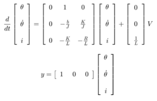
I think the 3 state system you linked is appropriate. I think this format is exactly what I’d use:
That said, because of the pole placement tuning method we use to tune the current controller, you could also treat the current as a 1st order system with the time constant 1/current_bandwidth.
Yes it’s basically voltage. Technically, the drive applies a duty cycle of the bus voltage, but we measure the bus voltage cycle-by-cycle and apply the duty cycle required to get the specified voltage.
I have the same question. Unless you have other sensors than the encoder, I don’t see why you need to run a different controller external to the ODrive? State space control is a linear feedback gain matrix on each state. If you multiply it out, our presently implemented control structure is also a linear gain on each state (current, position, and (estimated) velocity). You can derive the equivalent gains required for stock ODrive to perform the control specified by your LQR solution (or which method you will use to pick your gain matrix).
Should you still like to have the controller structured in the way you want, it’s probably still nicer to put that firmware on the ODrive than pull it out through an external microcontroller.
I had not seen this yet, thanks for pointing it out!
That is exactly what I wanted to do! Depending on the situation in which my system is and on the sensor setup that I have, I want to change the control strategy accordingly. I am yet to workout the details. You have a very good point is stating that the state feedback control gains can be translated into the equivalent gains of stock Odrive. Would the state estimation benefit from the implementation of a Kalman filter?
This generates a new question:
With this setup in mind, can the gains of the controllers be changed while the Odrive is running, or can you only set them when you flash the firmware on the drive?
I have been wondering the same about when to use the internal controller vs controlling the current directly.
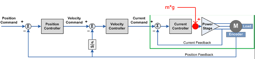
Lets say one where to build a robot arm for lifting and it needs to compensate for gravity. Then I would say it makes more sense to control the current directly to feedforward the gravity term to compensate for the effect of gravity.
For a simple pulley system consisting of a motor and a mass; am I correct in assuming that it is better to use current control and then calculate the current based on the desired force (gravity + acceleration force) instead of using the internal controller based on desired position trajectories?
What you are drawing is basically the same as Wetmelon said, just expressed in a more complete way.
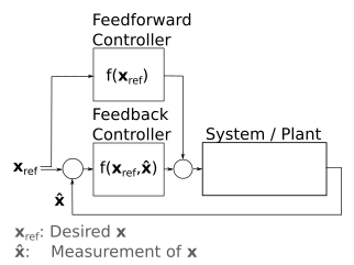
In the end, the feedfoward will depend on your desired setpoint. For example, if you want to compensate for static friction, the feedfoward for the current will be a non-linear function of your desired speed: current_ff = sign(speed_ref) * static_friction_coeff
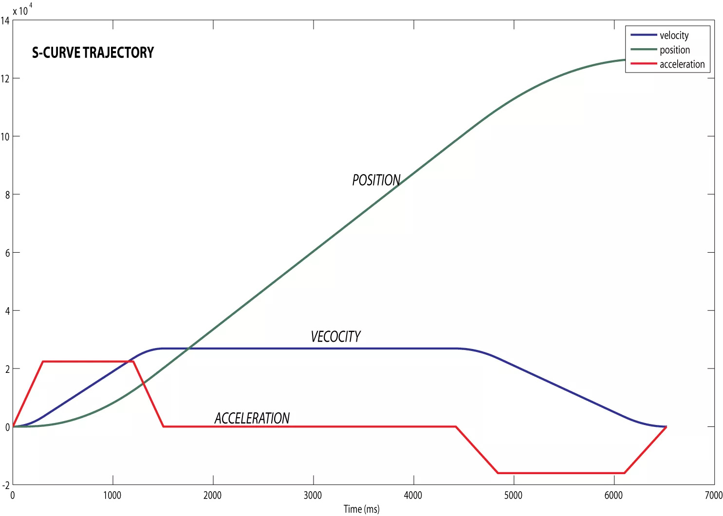
No, that’s incorrect. The FFs are generated off board, or by a trajectory planner (see the TrapezoidalTrajectory module in ODrive) Trapezoidal Trajectory Planner
the TrapTraj module generates three curves, and those curves are interpolated and used as the position setpoint and the Velocity and Current FFs. This one below is for an S curve, but the trapezoidal is similar