I’m looking to open a discussion about shielding. From my experience and research it seems that shielding should be connected on one end only. Usually on the target end (I.E. motor or machine end). Also make sure that your shield is not the same signal as your gnd. It looks like the encoder cable that is available in the store does not have the shield connected at all. Can anyone verify this for me? The reason for not connecting the shield at both ends is to prevent ground loops.
1 Like
Hi Bart,
The type of noise coupling that you are experiencing and the type of signal that is being carried affects whether you ground both ends of the shield or just one end.
There are two forms of coupling that can occur on electromagnetic systems and they depend on whether your circuit is coupling to the B or magnetic field of the noise source or the E or electric field of the noise source. The former is called inductive coupling with the latter being called capacitive coupling. Both types are present on drive systems. Capacitive coupled noise tends to be a lot higher in frequency when compared to inductive coupled noise and is more predominant due to the high frequency switching that is used for electric commutation of the motor.
The decision of whether to ground a single end or both ends of your signal cable depends on whether it is carrying digital or analog signals. For digital signals (such as an encoder) it is generally best practice to ground both ends of the shield because this best mitigates the capacitive coupling that I mention above. The ground loop currents that are generated typically don’t have as much of an effect on the digital signals. If the signal cable is carrying analog signals it is best practice to only ground the inverter end of the shielded cable.
That being said, the most effective mitigation is to ensure systematic physical separation of power and signal cables. If you have a power and signal cable running parallel to each other the full distance back to your ODrive then the noise will couple from the power cable to the signal cable. It’s just a matter of whether it will be enough to cause missed or extra counts on your encoder input. Separate the two cables as much as possible to reduce noise coupling between them.
It is also good to ensure you use cables that have finely stranded shielding and that shielding is clamped to your ground points using a large contact area. The fine stranding and large contact area ensure a low impedance path to ground for the high frequency noise that your shield is hopefully preventing from coupling onto your signal conductors.
Lastly, magnetic fields couple onto electric signals through cable loops. For this reason it is generally best practice to not loop excess cable as this increases the potential for inductive coupling to occur. If you have excess cabling it is best to use a zig zag pattern or something where you aren’t creating cable loops.
Ryan
2 Likes
One other point. It is usually also good to use finely stranded shielding on your motor power cables in addition to your signal cables. This has the effect of reducing the emission of noise rather than the reception. Two sides to the same problem.
Most of your hobby applications won’t have a nice conductive ground plane right underneath your machine like you see in most industrial applications. Without this, it is best to ensure a low inductance conduction path exists between your motor case and the odrive board. This is usually done by using shielded power cables and tying one end of the shield to the motor case and the other to the a grounding point on the odrive board using a large contact area at both connection points.
1 Like
I knew this would be a lively subject. I have done quite a bit of researching on this and there are a lot of considerations to think about. I am gonna let this simmer for a while and see what else people have to say about it. Does anyone know how the cable for the CUI AMT10 series is configured?
Definitely is a lively subject. I should say that all of the things that I mention above are considered best practice. Most of it is geared toward high voltage industrial applications where you are running the drives off of a 600-800 VDC bus. Not following best practice isn’t necessarily going to break your system, and things may be more forgiving at 48VDC, but if you do run into noise issues they can become real head scratchers. It’s rare when you run into a situation where you can immediately and with confidence claim that your system isn’t running right due to noise coupling onto your signals.
Hi Bart, I have been using 6 AMT encoders (AMT203) with 3 ODrives and the encoder cables are routed right next to the power cables without any shielding. Here are some things that I noticed:
- noise induced from switching was especially pronounced in the Z signal (not just spikes but you can see sqaure waves on the scope) and would almost always trigger “ERROR_CONTROL_DEADLINE_MISSED” (axis0 encoder Z pulse causing error in axis1 and vice versa)
- noise on A and B lines are definitely visible on the oscilloscope, but compared to Z pulse they are tiny jitters and wasn’t drifting the encoder counts on ODrive as far as I can confirm with AMT203’s absolute readings (I do have 150nF caps on A, B).
- Some motors cause a lot more noise in the encoder line than others.
I have one motor that vibrates when trying to hold position and it induces a lot more noise than others.
I am currently upgrading to use differential line drivers for encoder signals and was undecided if I should shield it or not cuz from my prior experience if the source of noise was like right next to the signal, shielding didn’t help as much as I expected and using differential signal was usually enough. But after reading what Ryan said I think I should experiment shielding the motor power cables with stranded stuff. Thanks, I didn’t know you can do that.
Where are the ground points on the ODrive board? https://raw.githubusercontent.com/madcowswe/ODriveHardware/master/v3/v3.5docs/v3.5_top.PNG
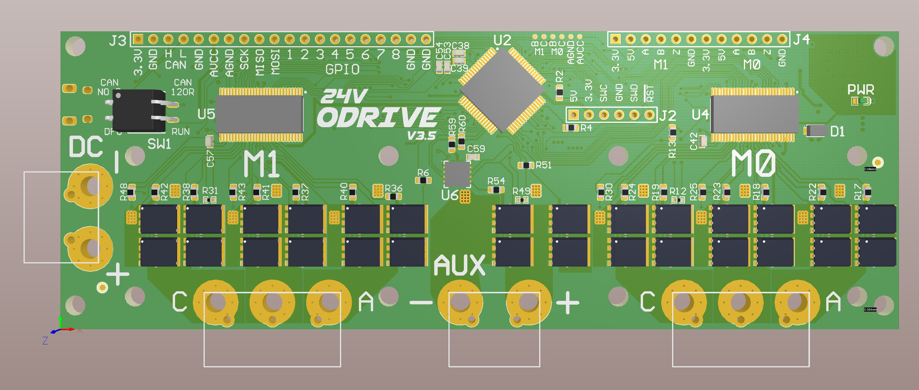