Hello, I’m in the process of setting up an encoder with an index signal following instructions on the https://docs.odriverobotics.com/encoders.html page on my V3.6 56V odrive system. I first followed the “Encoder with index signal” section, then made my way down to the “Startup sequence notes.” Unfortunately, I get an “ERROR_INVALID_STATE” when I get to the point where it says, “If calibration works, congratulations. Now try: .requested_state = AXIS_STATE_CLOSED_LOOP_CONTROL”. Here’s what I tried: 1) confirmed that the encoder works by using the encoder.shadow_count command and moving the motor in velocity control mode 2) Added a 47nF cap to the Z signal in case index signal was too noisy 3) re-ran the motor tuning process twice. Any help would be highly appreciated.
As a side question, is the system supposed to hold position (i.e. fight you) when the index search is executed at the start of boot? That’s not happening in my case and the index “exact” position seems to be inconsistent on successive boots (hence the reason for the 47nF cap addition thinking it was noise related). Thanks in advance!
The index search is open-loop i.e. the motor is behaving like a (microstepping) stepper motor. If you apply a load during this process, it may skip a pole and the index search will fail. You could try increasing the calibration_current value
If that fails, use an absolute encoder instead e.g. AS5047P with SPI interface. Then you don’t need to calibrate on startup.
Also, obviously make sure you have use_index=True, etc.
Thanks for your input towen. I increased the calibration current as you suggested and it did seem to improve the repeatability of the index position, albeit slightly. Of course, there is a trade off in that if you set it too high, it brings down your DC Bus-voltage resulting in an error. I ultimately ended-up at a calibration current of 20A with the power supply I’m using. That aside, I think I’ll resort to an endstop method to establish a “true starting position” at boot (of course once I figure out how to reflash my Odrive).
Regarding the “ERROR_INVALID_STATE” issue during an AXIS_STATE_CLOSED_LOOP_CONTROL function call, I found that the cause was related to an incorrect start-up sequence. I was under the impression that I did not need to do an ENCODER_OFFSET_CALIBRATION if I was using an encoder with index signal. Apparently I was wrong. To get passed this error, I executed the following sequence: 1) AXIS_STATE_MOTOR_CALIBRATION 2) AXIS_STATE_ENCODER_INDEX_SEARCH 3) AXIS_STATE_ENCODER_OFFSET_CALIBRATION 4) check if motor and encoder are read (i.e. motor.is_calibrated should be True and encoder.is_ready should be True) 5) AXIS_STATE_CLOSED_LOOP_CONTROL… check that errors are gone after this. 6) Set encoder and motor precalibrations to true (i.e. encoder.config.pre_calibrated = True, motor.config.pre_calibrated = True). After such sequence is followed, once can issue the .controller.set_vel_setpoint(3000,0 command to move/loop the motor. Hope this helps others that may be having similar issues.
So, I’m not sure that the odrive will be able to support initialising an encoder offset using an endstop switch. The reason for this is that an endstop switch is not always completely repeatable to within one encoder count (whereas an index pulse is) and the ODrive needs absolutely precise alignment of the encoder offset with the magnet poles, in order to be able to run the commutation algorithm.
Reflashing the ODrive is simple if you have built the firmware (i.e. you have a file called Firmware/build/ODriveFirmware.hex, after having run the ‘make’ command)
Thanks Tom. Totally understand what you mean about switch not being accurate. Actually, the plan was to wire the index signal to a GPIO and follow the endstop routines in the GIT to perform homing routines. The index search method is still not consistent despite increased calibration current… very jittery during seach movement and sometimes off by as much as 1 inch on an encoder with 4096 CPR.
Unfortunately, my encoder options are limited based on the motor and system setup that I’m using and so I cannot simply switch to a SPI based absolute version as you had earlier suggested.
If it’s jittery during an open-loop microstepping move with no load (i.e. during index search), then you probably have an extremely coggy motor. Is the motor difficult to move slowly and smoothly by hand and tends to snap to detent positions?
I would consider trying the anticogging features, but they are extremely experimental and still in development.
If it’s giving inconsistent index search results, then that probably means you have a noise problem - transient spikes are disturbing the index pulse. The index pin is interrupt driven, so it’s extremely sensitive to transients and capacitively coupled noise. Perhaps try putting a 1MHz low-pass filter instead of a capacitor on each of the encoder pins including index instead of just a capacitor (i.e. include appropriate series resistance) as suggested by @wtip in this thread.
Also, please make sure that you are using shielded and/or twisted cable where possible, and I would suggest grounding the motor chassis, and if possible route the encoder wires separately to the motor wires. You want to avoid coupling noise from the motor wires onto the encoder wires.
Motor wires should be twisted together, ideally with an earth wire and an overall shield.
Encoder wires should have an overall shield.
If you like, you could twist each A/B/Z signal with GND although that’s not strictly necessary since they are single-ended signals, not differential, but it should help.
Thanks Tom… I can resort to noise mitigation efforts. I have probed the signals in the past and they appeared good with decent rise times. I’ll recheck that now that my motor is tuned differently. One thing that’s interesting is that the jitter is intermittent. When it happens, it happens throughout the entire routine. When it doesn’t happen, it’s smooth all the way through. To answer your question, yes I can move the motor smoothly by hand and is not difficult to move. Now I haven’t tried moving the motor by hand during the execution of an index search routine… I suppose I can do that. Yes, the encoder cable is shielded and grounded to the encoder ground… encoder signals twisted appropriately and routed away from motor signals. Sure, no problem, I can implement a single pole low pass filter with a 1MHz cutoff to see if that makes a difference. Thanks for the pointer(s).
Hello Tom, I double checked the signals and all looks decent. No transients and the Index signal has a 5us risetime. I’ll do an infinite persistence measurement to double confirm that things are ok on successive trials (in case I got lucky on this one). Thanks
Moving the motor by hand during the index search might not be a good idea (unless perhaps you set calibration_current to 0)
I’m not sure, but maybe if you turn it by hand while in the idle state then it will find the index pulse without running the search routine? (you may need zero_count_on_index_pulse=True perhaps)
Was that scope trace taken during a failed index search? Or just turning by hand? Is there any noticeable increase in noise when the PWM is running? (i.e. closed loop control state or index search running)
Is your motor chassis properly grounded (so the encoder shield is not providing the low-impedance ground connection)
Stupid question, have you checked that the motor is securely attached? It seems strange that the open-loop microstepping is sometimes jerky, and other times not.
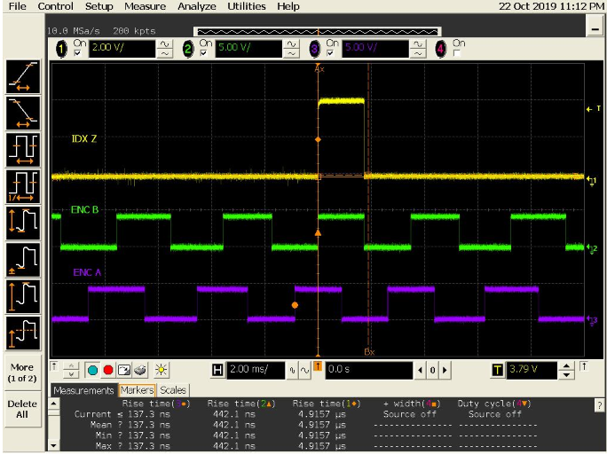
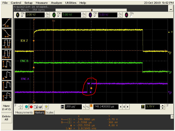
Thanks Tom for keeping the convo going… really appreciate the help thus far. That scope trace was taken on a passing index search. I did several attempts covering both passing and failing (i.e. overshoot by observable amount) cases and did not observe noisy transients. However, I did observe a glitch on ENC A during a failed-jittery-move case. See scopetrace 2. It’s worth noting that regardless of the index search routine, I’m still able to move the motor by specific encoder counts without issue in position mode, and at different RPMs in velocity mode
. I’m almost there, just need to guarantee that the motor / encoder starts at a given position at every start, hence the reason for bringing-up the end-stop homing idea.
Encoder is completely isolated from the motor (i.e. no physical connection), thus no low impedance return path through encoder shield (which ultimately would’ve showed up on scope traces as motor transients). Yes, the motor is securely mounted.
Now I will say, I do have a bit of mass (maybe 1/2 pound of weight) hanging on the motor at all times. Long story, but it has to be there. Perhaps the overshoot is happening due to the momentum involved. Unfortunately, I don’t have the luxury of removing the mass at every start-up. The system must always start with such mass and home to a specific position, consistently.
Well, I’ve fully transitioned away from noise mitigation techniques (at least for the moment since signals look pretty good) and am now transitioning to using end-stop homing routines.
Unfortunately, I’ve been unsuccessful in multiple attempts to reflash my 3.6 56V Odrive in both windows and linux environments. I’ve used all tools (except ST link) outlined in the instructions and have ran into several issues ranging from driver compatibility issues with windows 10 driver enforcement settings to ST tools not detecting the Odrive (e.g. DFuse not detecting STM bootloader / odrive). I’m now waiting for an ST link V2 to arrive to manually force a reflash. If that fails, then I’ll create a new topic.
If it’s just overshoot, then even after a “failed” index search, the motor should still be able to commutate properly - is that the case? If so then there is probably no issue. The index search shuts of the motor when it finds a pulse, and maybe the position that it coasts to afterwards is inconsistent. But if it has failed to get the proper index position then it will not enter closed-loop control, because it will fail to commutate properly.
After the “failed” index search, are the encoder counts zero?
If it has coasted away from the index, then they will be non-zero and you can just run controller.move_to_pos(0, False) to get back to a consistent position.
Re: flashing - I’m surprised you are having trouble… I don’t know about Windows, but under Linux, all I have to do is ensure I have the relevant Python packages installed (intelhex etc - Python will give you an ImportError if something is missing) and that I have permissions to use the device (either with udev rules, or by running odrivetool as sudo)
If the board is up and running with odrivetool, then it’s extremely unlikely that you require an STlink to flash it. Note that you do NOT need to set the DFU mode switch to flash it with odrivetool - it sends a command over USB to tell the ODrive to jump into to the DFU bootloader.
Thanks Tom. Yes, motor commutates as expected and moves to correct positions. I’ll make sure to issue a move to pos 0 command at every start to guarantee a known motor position at boot. Originally I had thought that the index search would set it there and maintain, but understand now that its an open loop routine and does not guarantee position at index. Would be nice to have that automatically done as part of the index search (at least for my case), but it’s no big deal to move to 0.
Now that indexing is working, I now have a new issue (aside from reflashing). Odrive is no longer detected by my PC when in Run Mode. Here’s what I did: I issued a velocity move, and while it was moving issued a move to position 0 command which resulted in a DC Bus undervoltage error. I cycled power and now my PC cannot detect the Odrive. Interestingly enough, setting the switch to DFU does trigger detection and shows up as STM BOOTLOADER WinUSB device. Setting back to RUN mode does nothing. Any thoughts on this one would be highly appreciative.
I’ve sometimes hit DC Bus undervoltage errors when trying to drive over 20A on my 56V ODrive - I think it probably needs extra DC Bus capacitance, that or very low impedance wiring to the power supply.
That’s sort of worrying that it didn’t come back after a power cycle. How did you cycle power? Some PSUs cause a nasty spike when you hit the mains switch.
Are you sure there isn’t another odrivetool running in the background which is grabbing the device?
Changing the DFU/RUN switch probably has no effect while the power is applied - I expect it’s only read by the bootloader on startup.
If you’ve got it into DFU mode then it should be possible to reflash or reset it with dfu-programmer (which is a standalone application rather than python/odrivetool)
After doing this, I was able to program via ST LINK without issue. Interestingly enough, the odrivetool dfu command still fails and so I’ve resorted to ST Link for now just to keep the development going.