I have a fdm printer which uses normal hybrid steppers to accelerate when printing up to 5g and when traveling up to 10-15g. Because of the limited supply voltage (back EMF) i am limited to a speed of about 400-500 mm/s. The travel acceleration and max speed is limited by the max torque and because of the back EMF the max torque drops with speed.
Therefore i wanted do push the limits using ODrive, that means more acceleration and more speed, because normal BLDC should not have a speed limit and a better torque/inertia ratio. For all who think that fdm is a “no load” application, i did choose the accelerations settings in a way that about 80 % of the max available torque is used. So there is enough load. Power is for sure low because of low revs.
For fdm applications the steady state setpoint error doesn´t matter at all because there is no steady state. Also high frequency noise on the position doesn´t matter, as long as there is no dominant frequency. But independently from moving fast or slow as soon as the setpoint deviation has any dominant low frequencies it will be visible. Accelerations and speeds are also quite high (for ODrive) as how below. The main problem ist trajectory tracking. In short terms an ODrive solution for fast (and by that non geared) belt driven fdm machines has severe problems with all above. The only part where ODrive can outperform the steppers is the steady state error - which does not give any benefit. I also had never problems with missing steps and there are much cheaper and reliable solutions.
So far with ODrive i am not able to achieve the open loop stepper performance and i am far away from outperforming it. The setpoint deviation with ODrive closed loop ist much bigger than with the open loop stepper. In my opinion it is a bandwidth/noise problem due to the PID-loops/cascades. A too low bandwidth of a PID-loop means, the gains are to small. It is typically for PID-loops, that there is a setpoint deviation if the setpoint is ramping. The faster the PID loop (especially the higher the D-part), the smaller the setpoint deviation.
At the beginning i also had the known cogging issues at low speeds (even with a NEMA23 3 phase hybrid stepper, which by itself cannot have these issues). Anti-cogging didn’t really help, it just added high freq noise, preventing increasing gains.
Luckily with increasing the encoder bandwidth to > 3000 rad/s (as well as the current bandwidth), the cogging problems could be more or less solved. Increasing the bandwidth enables the use of much higher gains, because otherwise the filter would interact with the PID-loop. Above 4000 rad/s the encoder bandwidth is limited by firmware and if the current bandwidth gets close to 4000 it is getting unreliable.
I did compare many and the following motors in more detail:
- NEMA17 2 phase hybrid stepper on Duet Wifi (reference, open loop)
- BLDC NTM Propdrive 35-36 on ODrive
- BLDC SK3 5065 on ODrive
- NEMA23 3 phase hybrid stepper on ODrive
All BLDCs as well as the NEMA23 performed without significant difference about the same. The higher the velocity the bigger is the position error and the bigger the gap to the open loop 2 phase NEMA17 on the Duet. The acceleration didn’t matter significantly. Even at 10g and 25600 mm/min (426 mm/s) the open loop stepper was better.
E.g. G1 X96 F9600 gives the following result with an 16384 encoder. I have to add that 16384 counts equals to 32 mm of travel. One 1/16th microstep to 0.01 mm or 5.12 counts. So a full step equals to 81.92 counts. The test was done on my test-bench. Load was the inertia of the motors - which is more or less the load in real life in my case.
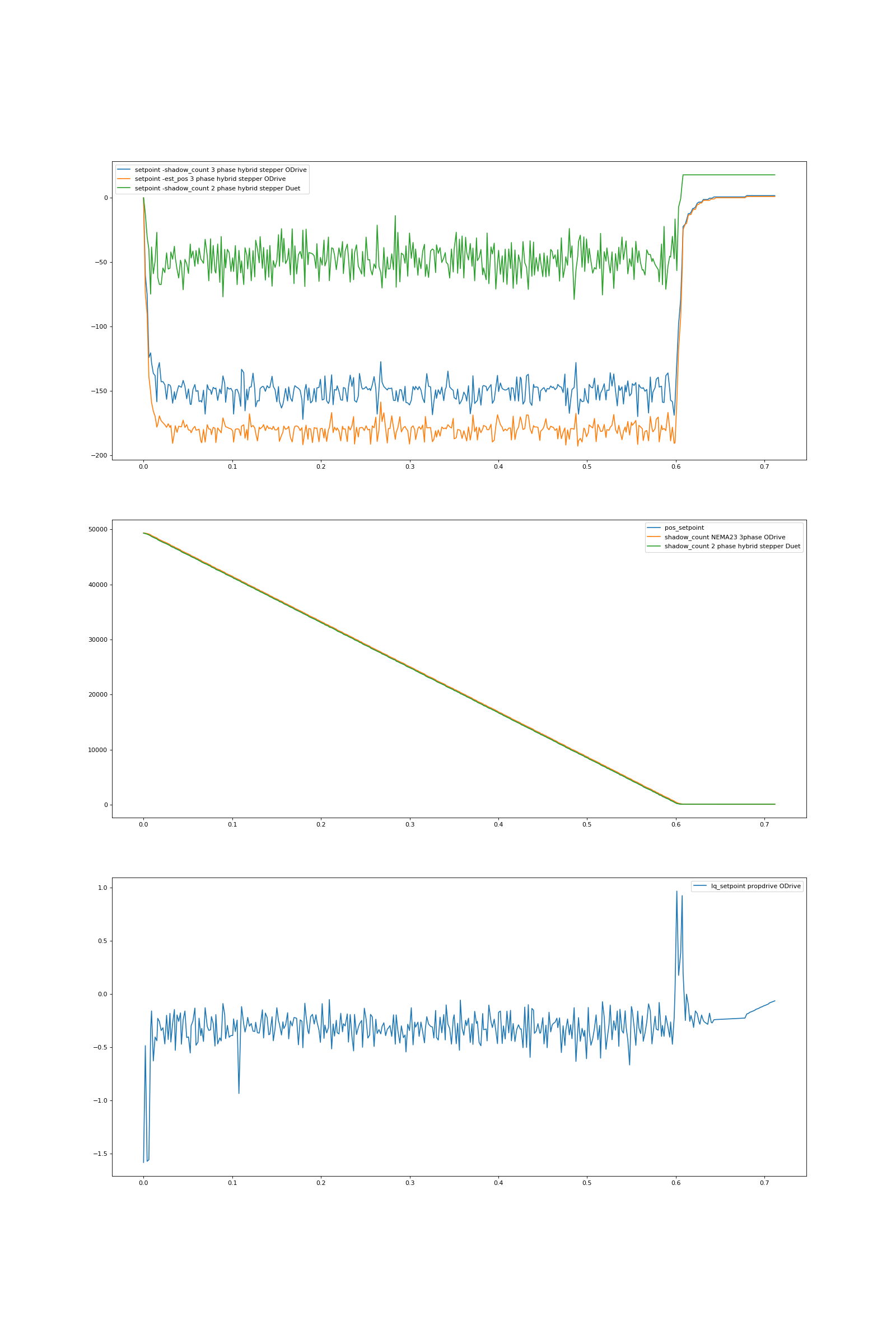
The 1st pic shows a tuning i could use in real life (but i didn’t really try).
- 1st axis green 2 phase hybrid stepper open loop on Duet position setpoint - shadow_count
- 1st axis orange 3 phase hybrid stepper ODrive setpoint - estimated_position
- 1st axis blue 3 phase hybrid stepper ODrive setpoint - shadow_count
- 2nd axis shows position
- 3rd axis shows iq_setpoint current 3 phase hybrid stepper
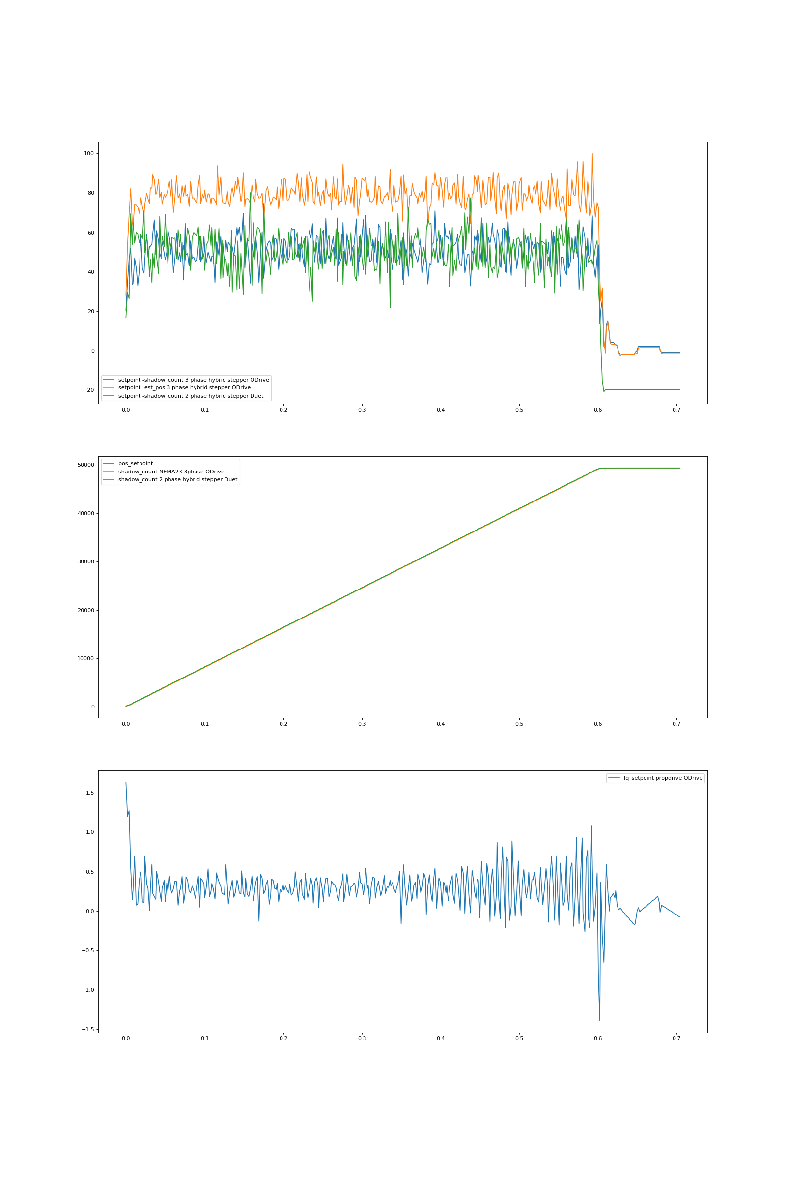
The 2nd pic shows a tuning which is much much too aggressive and only works sometimes, i could never even use it in real life, but i wanted to test, if by increasing gains (bandwidth) we could solve the problem. As shown in principle it works, but we are still not able to outperform the stepper and as mentioned, this tuning doesn’t work in real life.
G1 X96 F9600 turns the motor in total 3 times. at a speed of 5 rps (160 mm/s about my “normal” printing speed) with 2g acceleration in this case. Jerk was set to more or less 0 to sort out problems. With normal jerk values the BLDCs have even more troubles to keep up. The ODrive deviation increases quite linear with speed, a clear bandwidth problem indication. Although the “position noise” is smaller with ODrive, it doesn’t matter at all (you won´t see it) and it will get smaller under real conditions with more damping in open loop, but not so much in closed loop.
I did compare the “BLDC” NEMA23 hybrid stepper 3 because before increasing the encoder bandwidth, i couldn´t have used ODrive at all for fdm because of cogging. Because the NEMA23 hybrid stepper 3 phase cannot have a cogging issue by itself (otherwise hybrid stepper would not be used…), it was clear that it should perform best in this regard. I know that experts say from “a hybrid stepper cannot work at all with ODrive” to “it is experimental in best case”, it is no PMSM… I didn’t care, i just tested it and it performed at least as good as all the others and i have not been able to see any problem/difference. Cogging with the NEMA23 was much better compared to the others (no surprise).
Because it is a bandwidth problem, all kind of “gearing” the encoder won´t work, because we have to increase the ratio encoder_counts/noise. It would be cheaper just to buy a better encoder….
To investigate the influence of the encoder counts it did the following:
In general i use the CUI AMT 8192 encoders and it came out, that at 2048 CPR i could get slightly better results than on 8192 cpr, because i could use much higher gains - but by far not as high as theoretically possible. By reducing the the encoder pulse count by a factor of 4, without noise it should be possible to increase the pos_gain by factor of 4.
If with the same encoder, the encoder count is reduced by a factor of 4, the noise is reduced to 1/sqrt(4) = ½ and the velocity noise to sqrt(2)/sqrt(4)/4 = 0.177 (sqrt(2)*encoder_noise/dt). So in general the velocity noise level is sqrt(2) * encoder noise / dt bigger than the encoder noise itself. Higher counts mean lower dt and as well higher velocity noise.
So by reducing the encoder count i relaxed the velocity noise problem and could increase the vel_gain. This in combination with higher pos_gain leaded in the end a better total performance ! Although i couldn´t increase Kp by 4.
I also used a CUI 16384 cpr encoder instead of the 8192 one and i have not been able to improve results.
Some thoughts:
There is no benefit of running a PID-loop faster than 10-20 time of its bandwidth. But if there is noise and cascades and/or a D-part, a faster execution time will just amplify noise. I don´t know, but because there is only one “encoder_bandwidth” parameter, i assume that the encoder counts are only low pass filtered once and this goes into everything else.
The velocity loop must be about 5-10 times faster than the position loop to work reliably stable. if the position loop runs 10 times slower as the velocity loop, the encoder signal to the position loop should have 10 times less bandwidth, otherwise the noise gets just amplified by the gains and excites the velocity loop, which amplifies the noise again and bothers the current loop and so on. Because the vel_gain is the D-part, this is really bad and limits the use of high gains.
So how is the velocity (position) feedback term into the velocity loop filtered ? Is it just the encoder_bandwith ? What about applying a lower bandwidth filter to the position feedback ?
4000 rad/s equals to 637 Hz. What is the limitation of the current bandwidth - current noise ? Afaik the PID-loops run all at 8 kHz, could that be increased to use a higher current bandwidth ? It is clear the motor cannot response that fast but the problem is the PID-loop and not the motor itself.
Feedforwards especially inertia and speed should help in my case, but for all nonlinear printers like deltas, Hs, Corexy, scaras, etc. it won´t help much. Also for applying FF the input in the FF must be heavily filtered, reducing its benefit. In addition the official current firmware doesn’t support it. But maybe there is a much better solution.
gain scheduling vel_gain velocity loop:
Current equals to torque, so if a current is applied the inertia starts to accelerate. Depending on the ratio inertia / current it takes a while to achieve a certain speed change. The problem is, that this is highly nonlinear. The energy needed to accelerate an inertia from v1 to v2 is proportional to v2^2-v1^2. So if v1 = 0 and v2 = 2 the difference equals to 4. If v1 = 2 and v2 = 4, the difference in speed is also 2 but the needed energy 4^2-2^2 = 12 —> it is already 3 times bigger - which means it lasts 3 times longer to catch the setpoint. From that follows a linear PID loop cannot be tuned optimal for high and low speed regions. The low speed region will limit the gains preventing proper control at high speeds. Or in other words, the bandwidth of the whole PID-loop will decrease with high speeds - that is exactly what i see.
This problem could be overcome by gain scheduling. The proportional gain of the velocity loop should not be fixed, it should act like e.g. vel_gain = base_gain +abs(factor1 *(speed/base_speed)) + factor2 * (speed/base_speed)^2. So one term ~v^2 is for inertia and the other ~v for friction. I didn´t figure out how to set it in combination with the pos_gain, but that should be solvable. Also the input to gain scheduling needs to be filtered a lot.
I did a quick test in velocity control and tuned vel_gain always close to instability. A nice curve like below came out:
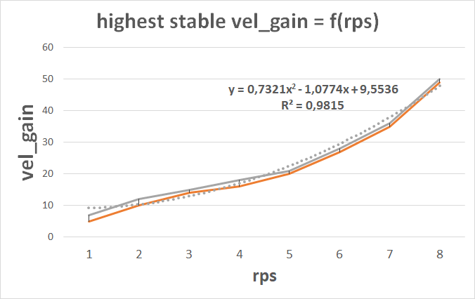
Because in position mode the vel_gain acts as the D-part, when ramping position, the D-part will add a constant current proportional to the speed. So it is nothing else as a velocity proportional feedforward. Therefore it is important to get it as high as possible to increase bandwidth.
 For everyone else, a PT1 is a simple single pole low pass filter
 I only have troubles at lower speeds now again. I guess in total the observer doesn´t give benefit as soon as enough counts/s arrive. I was able to reduce the low-speed ripple with anticogging. Anticogging also works with pos_estimate, should this be changed too ?