I got the same problem, I just downgraded to 0.5.1 again, because I don’t have the time atm to figure out what the problem is exactly. 0.5.1 works without problems.
Experiencing UART/ASCII issues (over GPIO1/2) after upgrading one of my odrives to 0.5.2:
Not entirely sure what’s happening but it seems like UART on the new firmware is more susceptible to electrical noise perhaps.
UART connection drops when odrive.axis is set to closed loop control state.
Even if only my other odrive (running 0.5.1) is set to closed loop control - the odrive running 0.5.2 stops sending data over UART.
The odrive (running 0.5.2) must be reboot or power cycled before the UART/ASCII protocol starts working again - ie just removing the electrical noise doesn’t seem to correct the issue.
Note: not using checksum in ascii protocol.
I noticed the release page states: " * ASCII and the Native Protocol do not run at the same time on a UART interface. See odrv0.config.uart0_protocol and the STREAM_PROTOCOL_TYPE enums for details." - not sure if that’s relevant or not.
Unfortunately I cannot proceed with my project with 0.5.2 until this issue is resolved - so rolling back to 0.5.1.
Anyone else experiencing anything like this?
EDIT0: problem persists if reconfigured using UART1 with GPIO3/4.
Awesome, updates are always welcome.
But for some reason my settings can’t be saved?
odrv0.save_configuration()
Returns a False, why and how?
Another question:
How do I change
odrv0.config.gpio1_pwm_mapping.endpoint = odrv0.axis0.controller._remote_attributes[‘input_pos’]
To the new 0.5.2, is this correct?
odrv0.config.gpio1_pwm_mapping.endpoint = odrv0.axis0.controller._input_pos_property
Was the motor armed when you tried this? If yes, this is expected. If not, do you have an STLink debugger? With that you could investigate which of these three functions fails, and where.
Yes.
1 Like
Hi,
After upgrading the firmware v0.5.1 to v0.5.2, whenever I exit the Odrivetool (with command quit() or exit()) I always got the error:
Task was destroyed but it is pending!
task: <Task pending coro=<_Domain.run_discovery..loop() running at /usr/local/lib/python3.6/dist-packages/odrive/pyfibre/fibre/libfibre.py:963> wait_for=<Future pending cb=[<TaskWakeupMethWrapper object at 0x7fadac81c8>()]>>
I have already downgraded firmware to 0.5.1 but the control utility version is still the v0.5.2.
Please help me to install back control utility version 0.5.1 or get rid of the error. Thank you!
There was some refactoring around the UART & ASCII code so it’s possible that a bug was introduced there. We have a test case that injects noise into the UART RX but this test case passes on 0.5.2.
Here are some suggestions:
- Are you using
STREAM_PROTOCOL_TYPE_ASCIIorSTREAM_PROTOCOL_TYPE_ASCII_AND_STDOUT(default)? See if the issue occurs with the other setting too. - What commands are you sending on UART? If it’s more than one periodic command, see if it still persists if you reduce it to a single command.
- Is the ODrive still responsive on USB when UART locks up? Does
odrv0.system_stats.uptimestill increment? - Do you have the ability to debug with an STLink? If yes, you can:
- define a variable
volatile int last_pos = 0;somewhere in the code - scatter
last_pos = __LINE__;throughout the UART code (primarily interface_uart.cpp, ascii_protocol.cpp) - run with the debugger. Once UART locks up, pause the firmware and inspect the value of
last_pos.
- define a variable
For the record, here’s the relevant diff.
@marklee56826 this error is harmless but I understand that it’s distracting so I can have a look if we can get rid of it.
Thanks @Samuel !
Problems solved, putting both Axis in idle before saving does the job!
And after setting the odrv0.config.gpio1_mode = 10 #GPIO_MODE_PWM it works like a charm!
2 Likes
Thank you for your kind reply, but could you tell me how to remove control utility version 0.5.2 and install back control utility version 0.5.1? There is no such problem with version 0.5.1. Thank you.
pip install 'odrive==0.5.1.post0'
Hi all, I just updated the Odrive control utility to 0.5.2 as well as the firmware, and I noticed that the Iq setpoint was saturated at 3.3333334922790527.
I am using a 4S lipo battery to drive a motor similar to T-motor U10plus.
I set up the ODrive motor controller in torque control mode
The motor configuration and controller configuration are listed below:
I_bus_hard_max: inf (float)
I_bus_hard_min: -inf (float)
I_leak_max: 0.10000000149011612 (float)
R_wL_FF_enable: False (bool)
acim_autoflux_attack_gain: 10.0 (float)
acim_autoflux_decay_gain: 1.0 (float)
acim_autoflux_enable: False (bool)
acim_autoflux_min_Id: 10.0 (float)
acim_gain_min_flux: 10.0 (float)
bEMF_FF_enable: False (bool)
calibration_current: 10.0 (float)
current_control_bandwidth: 1000.0 (float)
current_lim: 60.0 (float)
current_lim_margin: 8.0 (float)
dc_calib_tau: 0.20000000298023224 (float)
inverter_temp_limit_lower: 100.0 (float)
inverter_temp_limit_upper: 120.0 (float)
motor_type: 0 (uint8)
phase_inductance: 2.2307487597572617e-05 (float)
phase_resistance: 0.0595686137676239 (float)
pole_pairs: 20 (int32)
pre_calibrated: False (bool)
requested_current_range: 90.0 (float)
resistance_calib_max_voltage: 2.0 (float)
torque_constant: 1.0 (float)
torque_lim: inf (float)
anticogging:
anticogging_enabled: True (bool)
calib_anticogging: False (bool)
calib_pos_threshold: 1.0 (float)
calib_vel_threshold: 1.0 (float)
cogging_ratio: 1.0 (float)
index: 0 (uint32)
pre_calibrated: False (bool)
axis_to_mirror: 255 (uint8)
circular_setpoint_range: 1.0 (float)
circular_setpoints: False (bool)
control_mode: 1 (uint8)
electrical_power_bandwidth: 20.0 (float)
enable_current_mode_vel_limit: True (bool)
enable_gain_scheduling: False (bool)
enable_overspeed_error: True (bool)
enable_vel_limit: True (bool)
gain_scheduling_width: 10.0 (float)
homing_speed: 0.25 (float)
inertia: 0.0 (float)
input_filter_bandwidth: 2.0 (float)
input_mode: 1 (uint8)
load_encoder_axis: 0 (uint8)
mechanical_power_bandwidth: 20.0 (float)
mirror_ratio: 1.0 (float)
pos_gain: 20.0 (float)
spinout_electrical_power_threshold: 10.0 (float)
spinout_mechanical_power_threshold: -10.0 (float)
steps_per_circular_range: 1024 (int32)
torque_mirror_ratio: 0.0 (float)
torque_ramp_rate: 0.009999999776482582 (float)
vel_gain: 0.1666666716337204 (float)
vel_integrator_gain: 0.3333333432674408 (float)
vel_limit: 20.0 (float)
vel_limit_tolerance: 1.2000000476837158 (float)
vel_ramp_rate: 1.0 (float)
and here is the input torque as well as Iq setpoint during operation
In [33]: odrv0.axis0.motor.current_control.Iq_setpoint
Out[33]: 3.3333334922790527
In [34]: odrv0.axis0.controller.input_torque
Out[34]: -9.652692794799805
Maybe this issue has existed before when I was using 0.4.12, but I was wondering if there is any other parameters that I should set to increase the current.
Best.
Sounds like an encoder problem, i.e. the commutation is wrong.
What encoder are you using? Can you check that is working properly? (try using odrivetool liveplotter and turn the motor by hand)
Hey,
We’re experiencing issues when initiating closed loop control from the startup sequence. Whenever we try to actuate the error UNKNOWN_PHASE_ESTIMATE is given. If we manually set the axes to closed loop control we don’t experience this error.
I’m honestly not sure whether this issue has arisen from the firmware changes as we haven’t used this feature with earlier firmware version. Though I’d expect it to be a known issue if it had occurred in earlier firmware versions.
Cheers
1 Like
Try disabling the speed limit in torque mode (controller.config.enable_current_mode_vel_limit)
I’ve created a github issue for this, please put any info you have in there. startup_closed_loop causes UNKNOWN_PHASE_ERROR · Issue #582 · odriverobotics/ODrive · GitHub
Was there any change related to pre-calibration data for the encoders?
Namely, requesting state AXIS_STATE_ENCODER_INDEX_SEARCH doesn’t actuate the motor as it did in 0.5.1. However, one can request AXIS_STATE_CLOSED_LOOP_CONTROL immediately afterwards and the drive actually goes into closed loop control - then, if the motor is disturbed in any way, MOTOR_ERROR_SYSTEM_LEVEL and ODRIVE_ERROR_DC_BUS_OVER_REGEN_CURRENT are generated…
We are also experiencing issues activating step/dir input mode
- disabled UART on pins 1,2,
- switched the pins to mode 0 (GPIO),
- enabled step_dir in axis config
- checked for correct step and direction gpio mapping in axis config
Is there anything else to check/do?
We upgraded the FW to 0.5.2 due to LPF on motor thermistors (we had an issue that in one moment odrive with 0.5.1 went into a weird state, where the stationary and unloaded motor got so hot it burned the skin on touch…).
ps: anti-cogging calibration is not operational, either… odrv0.axis0.controller.start_anticogging_calibration() sets the calib_anticogging: True, but there is absolutely no motion after initial ‘jerk’ to the starting position
Hi,
I ran a firmware update using multi-platform instructions posted on the odriverobotics site. I was running into many issue and am now trying to go back to the 0.5.1 firmware version.
I downloaded the folder from github and it is sitting in my downloads and I am not quite sure where to move the folder from there. I was wondering if anyone knew what file location it should be placed in?
Hey guys, I am using a motor with hall sensors built in and I am having getting position control working. I can get velocity control working when I am in incremental encoder mode, but when I change to hall encoder mode, I can’t get position control working.
One thing I am confused about is what’s the difference between hall encoder mode and incremental? The screenshot below says I need to put it in incremental mode, but I think I want to get it working in Hall mode.
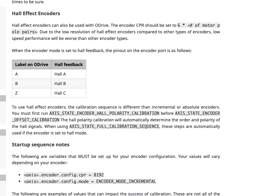
Another thing, the screenshot below says to configure GPIO pins 9,10,11 to digital, but in Odrive now, I get an error like AttributeError: Attribute gpio9_mode not found when trying to perform the commands below.
.config.gpio9_mode = GPIO_MODE_DIGITAL
.config.gpio10_mode = GPIO_MODE_DIGITAL
.config.gpio11_mode = GPIO_MODE_DIGITAL
Thanks for all the help!
@MatevzB what command sequence did you use for setup?
I tried this and it works as expected:
odrv0.erase_configuration()
odrv0.axis0.encoder.config.use_index = True
odrv0.axis0.requested_state = AXIS_STATE_MOTOR_CALIBRATION
# [wait for beep]
odrv0.axis0.requested_state = AXIS_STATE_ENCODER_INDEX_SEARCH
# [wait for motor to stop]
odrv0.axis0.encoder.index_found # returns True
odrv0.axis0.requested_state = AXIS_STATE_ENCODER_OFFSET_CALIBRATION
# [wait for motor to stop]
odrv0.axis0.encoder.config.pre_calibrated = True
odrv0.axis0.motor.config.pre_calibrated = True
odrv0.save_configuration()
# [wait for reboot]
odrv0.axis0.encoder.index_found # returns False
odrv0.axis0.requested_state = AXIS_STATE_CLOSED_LOOP_CONTROL
odrv0.axis0.current_state # returns 1 (idle)
odrv0.axis0.requested_state = AXIS_STATE_ENCODER_INDEX_SEARCH
odrv0.axis0.encoder.index_found # returns True
odrv0.axis0.requested_state = AXIS_STATE_CLOSED_LOOP_CONTROL
odrv0.axis0.current_state # returns 8 (closed loop control)
As for the anticogging and step/dir issues, I have to look into that.
@vvanamala you can point odrivetool to the path where your downloaded hex file is: odrivetool dfu /path/to/firmware.hex.
@ap23 can you post the output of odrv0.config? Does it contain an item called gpio9_mode?
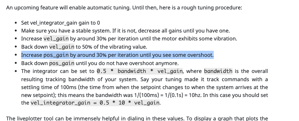
@Samuel We ended up figuring this out, it turns out we didn’t need to set those GPIO pins to digital. However, now we got position control to work but are having a little trouble with tuning our system.
In the tuning instructions below, it says to increase position gain until it overshoots. Does this mean the. motor has to already be spinning during tuning? Do we need to give it an input position before tuning? What exactly does overshoot mean in this context? Thanks a lot! Also, I’m having an issue where sometimes i need to give the motor a small tap before it goes to the commanded position. Is there any way to fix this?