FOC controlled Stepper Motors are better suited for our application
Stepper motors have more torque than BLDC motors, but are they less efficient?
The way stepper motors are used today they are lossy and have problems like “loosing steps”, since they are commutated completely blindly - no hall sensors, no zero voltage crossing detection or current analysis. No feedback at all. Surprisingly, they still work fine in most cases where huge torque is demanded, even in “blind mode”. The reason is, they were designed to work this way: They were designed for most torque and most simple driving. The torque density they archive still is unbeaten, but the way we drive them can be done way better today – even without any encoders or sensors – the keyword is FOC for hybrid steppers, which works without sensors besides the current sensors in the controller.
Hybrid steppers are a bit like BLDC motors with very high pole count that use reluctance and permanent magnetic forces at the same time – the reason they are called “hybrid” steppers. Almost all stepper motors used today are Hybrid Steppers. They are no true reluctance motors but have permanent magnets, just like BLDC motors or brushed DC motors do, thus they have a back EMF, a voltage that is generated if you turn the shaft. This voltage can be detected, unlike true reluctance motors that are turned by their “soft magnetic” properties, without permanent magnets, without any voltage generated if you turn the shaft.
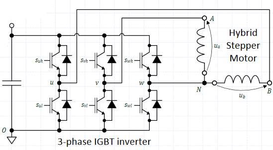
ODrive can drive BLDC motors with or without any encoder. It assumes the actual rotor angle by measuring the motor currents and thus uses the motor itself as a sensor [citation], a sensorless operation. Hybrid stepper motors can be treated almost the same, with two phases instead of three:
Are you sure that the torque density of a stepper motors is really that much better than that of a BLDC motor? For example compare a Nema23 stepper motor from Pololu with a Hudson-series M-2310 Clearpath servo motor. Both motors have roughly the same frame size and yet the stepper is nearly twice the weight of the servo at 1.05 kg vs 0.63 kg while producing around 30 % less holding torque at 1.9 and 2.7 Nm respectively.
Either way, thanks for the post as it has got me reading up more on FOC. I found this to be a great source of information. I have no idea if it can be applied to a sensorless hybrid stepper but it does sound interseting.
Thanks for the papers and theory, I find this kind of stuff very interesting.
My research has shown that the torque of PMSM’s is usually better per unit cost, weight and volume. For example, I compared the 23Y206S-LW8 with the N5065 - 270kv. But if you have data for a counterexample that would be interesting to look at.
That said, I think there is some scope for a driver that does sensor-less FOC control of stepper motors, especially for drop-in replacement on existing machines.
If you compare inrunners like the 23Y206S-LW8 with outrunners like the N5065, the outrunner will always win due the larger airgap diameter for a given outer diameter. But you would not want to use a motor like the N5065 in a CNC lathe or mill, as bearing life of these motors is very short (tiny bearings) and they are hard to keep cool when they are enclosed so no shavings can get into them.
If you compare for example a Nema BLDC and a Nema 2-phase hybrid stepper, the hybrid stepper will always win due its higher field utilization: The reluctance forces add up to the Lorentz forces.
Example: A Nema23, 76mm long motors, exactly the same size and weight:
As a rule of thumb, those Hobbyking ratings can be divided by ~3 to get a realistic rating of the actual torque or power these outrunner motors are capable of in a CNC setup. For example a N6374 which can do ~4Nm with a prop drive for a short time. Or it can do around 1.3 Nm in a CNC setup, where it would be around 75mm in diameter with housing. But the bearings might fail after a couple of thousand hours - or even after just a few hundred if the load distribution of the drive is bad. The above mentioned Nema23 hybrid stepper is cheaper, smaller and more lightweight compared to the hobbyking drive. Cost is about half for the Nema23
I have a couple of N6374 in an electric skateboard and an ebike an i must admit the bearings are not up to the task. The space this outrunner design allows is just too small to fit a properly sized bearing. That’s why i like to use a slightly different design for such outrunners that are nice drives for vehicles. Something with a non-rotating axle like a ebike hubmotor. Check out my belt drive design: https://endless-sphere.com/forums/viewtopic.php?f=28&t=80516&sid=31ed82022cc341ca5355b2bede010c5a&start=175#p1281430
Anyway, back to topic. I think we could use the ODrive to drive Hybrid-Steppers with FOC, i’d like to try it when i find the time for it .
Nice apples to apples comparison there, and good point about inrunners vs outrunners and the flux gap diameter.
Overall I can agree with you that for applications where gearing for faster PMSM’s is not an option, there may indeed be a space for steppers.
Another thing that may be important is that steppers are rated to run their rated current all the time, so peak torque and continous toruqe are basically the same. But when you start doing FOC, you can let the motor run much cooler overall, and can absorb higher thermal output in peak current, and should translate to being able to push over rated current and rated torque without much issue.
Nice motor and linear actuator design over at endless-sphere! I have a couple of comments and questions about it, but in the interest of staying on topic about FOC of steppers in this thread I’ll just ask over there.
You can put about 4A peak in a normal NEMA 17. But the torque does not scale linear with current because of flux saturation.
Sensorless FOC and using the reluctance torque is a bit more complex.
Driving steppers with 3phase inverters limits your phase voltage to about 70%.
With modified clarke transformation the normal pmsm control loop works for steppers.
ODrive v3 is not optimal for normal sized steppers because of the high adc noise and max current.
Is it not also the case that stepper motors will be less efficient than PMSM? Some amount of energy will be going into creating eddy currents in the ferromagnetic material.
I’m a fan of keeping things simple For CNC machines steppers may be the better choice. Ttill last week i wasnt aware of FOC for steppers. I saw a lots of BLDCs in CNC machines, and when I asked the people who built them why they use BLDCs instead of Steppers, they told me that BLDCs where more precise and more quiet since they are driven with FOC. Now i ask myself if they just didn’t know better and if FOC driven Steppers arent a better choice for applications where high accuracy and low rpm are needed.
Hey, that is good to hear! How can I get hands on such a stepper driver?
OK. So just the way it is shown in the diagram in post 1? That would be nice.
Would a different shunt help? As less current is needed, a higher value shunt could be used. Or is it the way currents are measured using the low side shunts?
Common steppers have more poles than common BLDCs, and eddy current loss depends on pole count and rpm. So they should have higher eddy current loss for the same rpm, just like a BLDC with high pole count would have.
BLDCs with buried magnets also produce reluctance torque. So to me it looks like a hgybrid stepper is similar to a BLDCs motor with buried magnets and very high pole count.
eddy currents will occur in every motor with a changing magnetic field.
For the same shaft speed a stepper will have more eddy losses than a normal bldc due to the higher pole count. But the stepper has a higher torque density.
The stepper has the advantage of being dirty cheap.
If we ignore sensorless stuff you need accurate position feedback to drive a bldc with FOC. So you can position it more precise than an open loop stepper.
But a stepper with the same feedback will give you the same result.
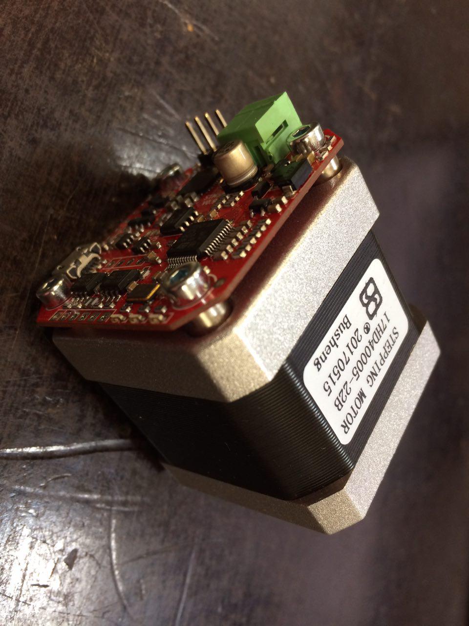
Its side project of stmbl thats just did it’s first steps a week ago (; Hardware Firmware
It’s based on stm32f303, l6206q and tle5012.
Specs: 12-48V, 5A peak, 15bit abs. encoder
So it’s like a mechaduino or NZS with better hardware and software and without arduino.
Any chance to meet you at Hackover, Motek or 34c3?
Yes.
10x should work.
The bandwith of the current amplifiers is too low for higher pwm frequencies. So you are limited to bigger motors with a long electrical time constant.
This should be fixed in the next revision.
I spent some time investigating and learning about FOC using stepper motors, and I wanted to share some of my findings here. I focused on a bipolar hybrid stepper implementation, but extrapolations to other stepper motor topologies should be obvious. Feel free to comment if something I say here seems wrong; I don’t have a strong background in hardware-level motor control.
Pros:
Mounting NEMA stepper motors is common/cheap
Because the effective number of poles on a stepper motor is very high, it has exceptionally high torque and higher torque per cost than comparable BLDCs
Torque available via FOC on steppers can easily be high enough to not necessitate gearing
Control loop transforms (e.g. Park) are simpler for bipolar stepper motors
Bipolar steppers only require 2 full H bridges to drive in FOC
Cons:
Because the common bipolar stepper motor only has 2 phases that are 90 degrees out of phase, the normal 15.5% voltage boost that SVM offers isn’t available
Because the effective number of poles on a stepper motor is very high, a high resolution encoder is needed to give reasonable FOC performance. For a 60° BLDC phase, ±5° position error is usually acceptable, which makes 360°/5° = 72CPR encoders feasible. It’s common to want higher positional control than that, but it’s not required. For a 0.9degree stepper, a 1/12 phase error is ±0.075° error, which means 360°/0.075° = 4800CPR/1200PPR encoders would be required (minimum). This almost always means increased cost
Because the effective number of poles on a stepper motor is very high, time between control loop updates should be much quicker than its BLDC counterpart else the effectiveness of FOC drops dramatically due to being slow
Control loop transforms (e.g. Park) are simpler for bipolar stepper motors
Not much difference there. Just some constant multiplications.
Bipolar steppers only require 2 full H bridges to drive in FOC
Same for open loop steppers. 3PH steppers or BLDCs only need 1.5.
Because the common bipolar stepper motor only has 2 phases that are 90 degrees out of phase, the normal 15.5% voltage boost that SVM offers isn’t available
2PH SVM gives you 41% more phase voltage or 100% if you use overmodulation.
Because the effective number of poles on a stepper motor is very high, a high resolution encoder is needed to give reasonable FOC performance. …
Keep in mind, that open loop steppers are only accurate to about ± 1 step.
If your application needs an encoder for more accuracy you can do FOC for “free”.
A magnetic absolute encoder with > 12Bit resolution cost about 5€.
For comparison: most industrial style servos system use 13Bit (the cheap stuff) to 24Bit resolution / turn.
For velocity based application you can use sensorless FOC.
Because the effective number of poles on a stepper motor is very high, time between control loop updates should be much quicker than its BLDC counterpart …
Yes, but in the same application the stepper would turn slower because it does not need a reduction for the same torque.
In the end steppers have more torque / price but less speed.
And it depends on your application if a stepper or bldc is better.
A magnetic absolute encoder with > 12Bit resolution cost about 5€.
Yes but the ones I’ve seen have significant latency, or unrated latency. If you have a part you think would work well, I’d be interested in it.
2PH SVM gives you 41% more phase voltage or 100% if you use overmodulation.
Makes sense! Sorry if I miss something obvious, these things aren’t intuitive to me yet.
Yes, but in the same application the stepper would turn slower because it does not need a reduction for the same torque.
Agreed. I didn’t mean to undervalue this “pro”. Not requiring gearing is a big deal.
And it depends on your application if a stepper or bldc is better.
For CNC axis applications, I think steppers are pretty defensible unless you have large effective rotor inertia. I plan on putting together a simple FOC stepper implementation to see how its real performance is.
Does anyone know how BLDC vs hybrid stepper compare on the following points?
Continuous torque as a fraction of peak
Torque vs rotor inertia
Cogging torque
Also @crinq, about the latency compensation. Presumably this only works if your speed in pretty much constant? Presumably latency compensation doesn’t work in very dynamic situations. What sort of latency are we talking here? microseconds, ms?
what’s the conceptual difference between a BLDC that has lots of poles and a
stepper motor?
I believe that the primary difference boils down to the technical implementation
details of star vs separate coil wiring.
A Cogging BLDC is basically being run like a stepper at full step. And if you
run a stepper with enough microsteps and fast enough, it really starts to
resemble a BLDC waveform.
There is enough variation in motors, that you can find low-resolution steppers
and high resolution BLDCs that cross in just about anything you measure.
 .
.
 For CNC machines steppers may be the better choice. Ttill last week i wasnt aware of FOC for steppers. I saw a lots of BLDCs in CNC machines, and when I asked the people who built them why they use BLDCs instead of Steppers, they told me that BLDCs where more precise and more quiet since they are driven with FOC. Now i ask myself if they just didn’t know better and if FOC driven Steppers arent a better choice for applications where high accuracy and low rpm are needed.