Grounding issue on the left side of the board

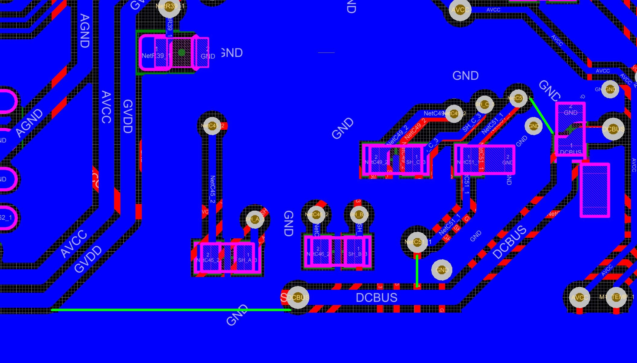
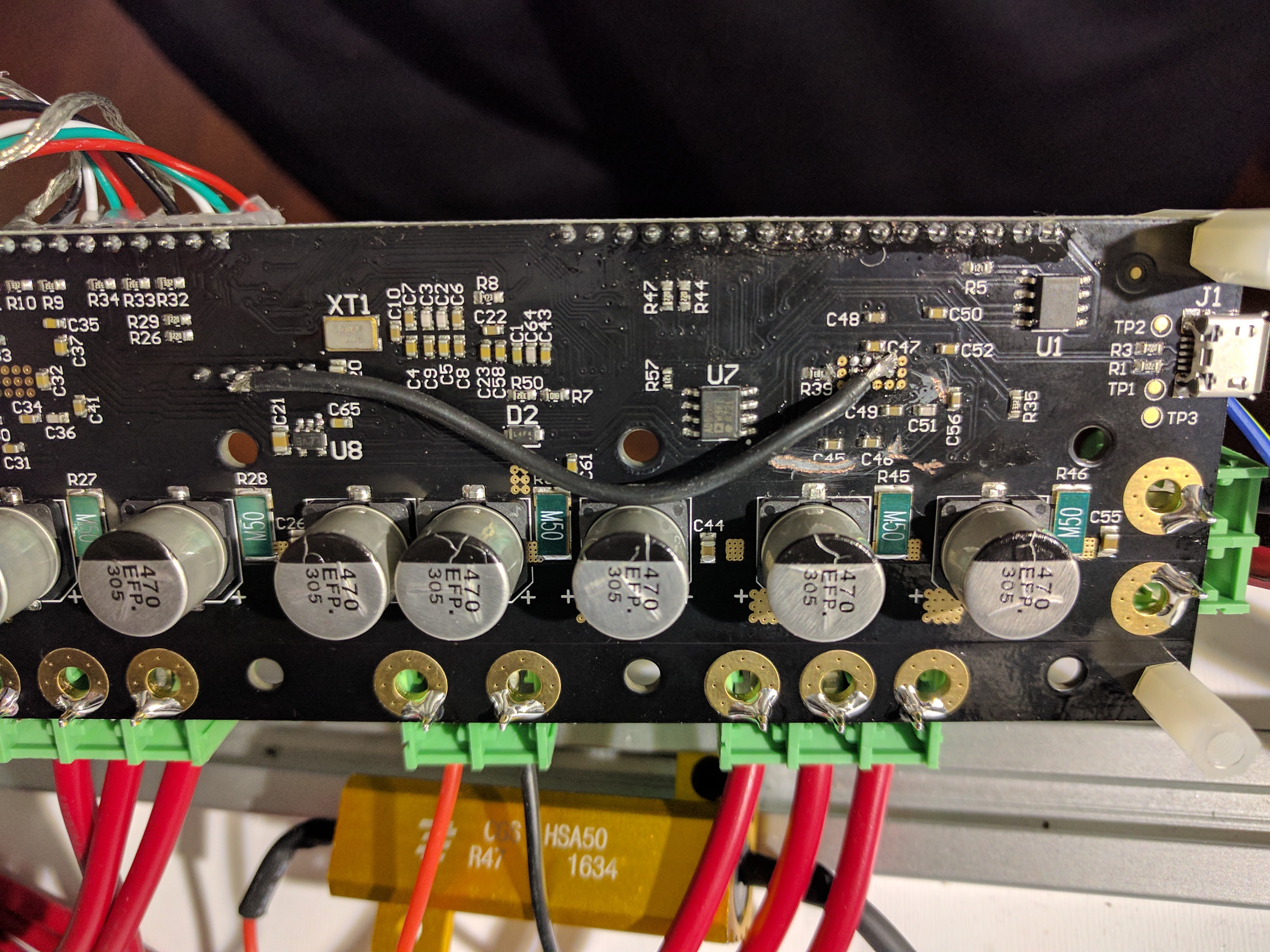
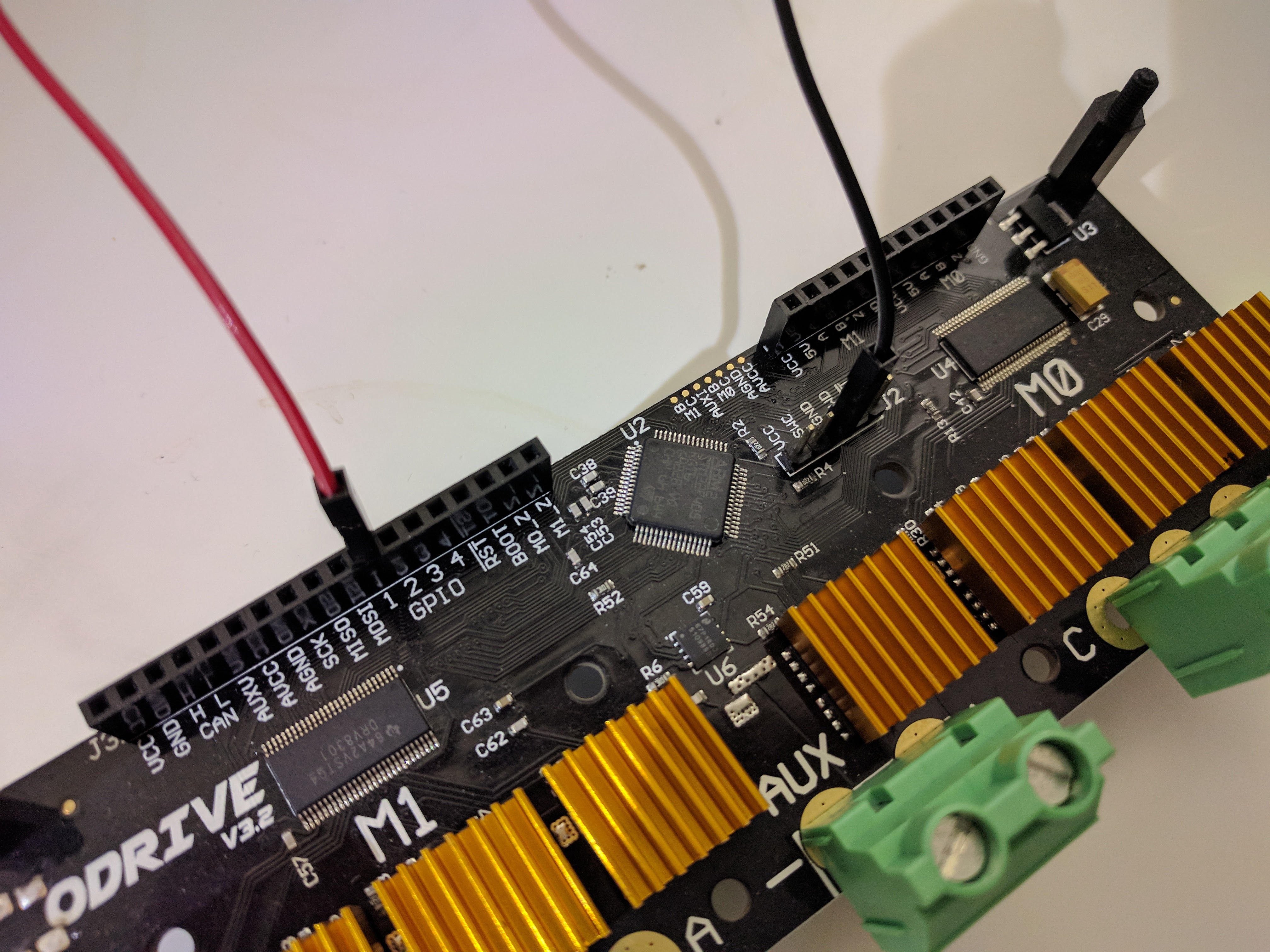
With the help of testing efforts by the community, we have uncovered an electrical issue with the ODrive (v3.3 and earlier). The GND of left side of the board is connected to the GND of the right side of the board through the main power ground bus, as can be seen as the blue horizontal area in the image below:

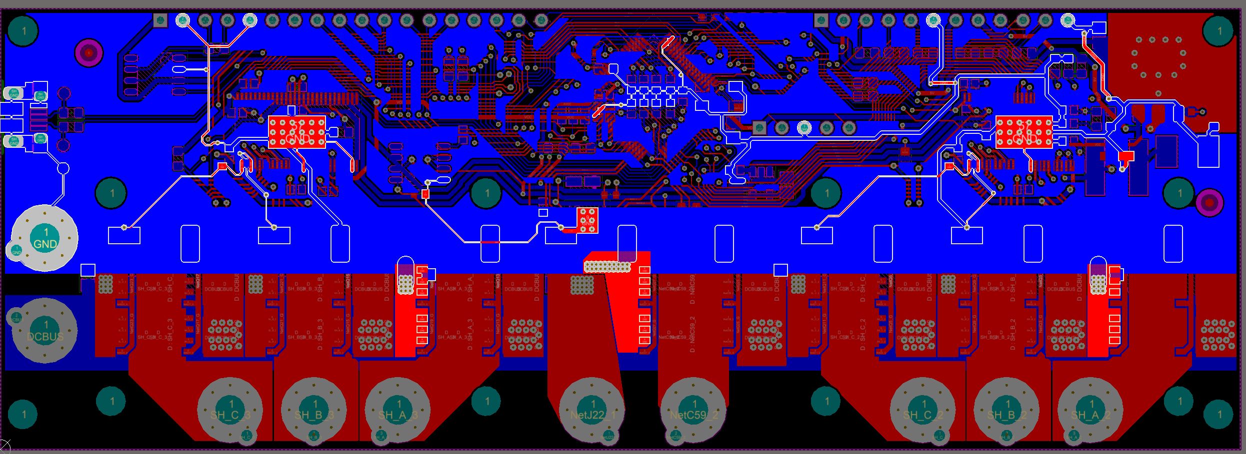
Highlighted is the GND net (shematics here for reference).

This thick ground bus is very low impedance, and even with very high currents, the voltage drop across it will only be 10’s of mV. Therefore it was deemed okay to connect the grounds in this way. However, as was revealed, the inductance of the same path is significant enough to cause problems.

As the MOSFETs switch, this causes large dI/dt in various segments of the ground bus, and hence voltage drops across the segments. Since the ground traces of the left part of the board is tapped from a different place than the right side, it causes the grounds to see voltage spikes with respect to each other.

Measurements

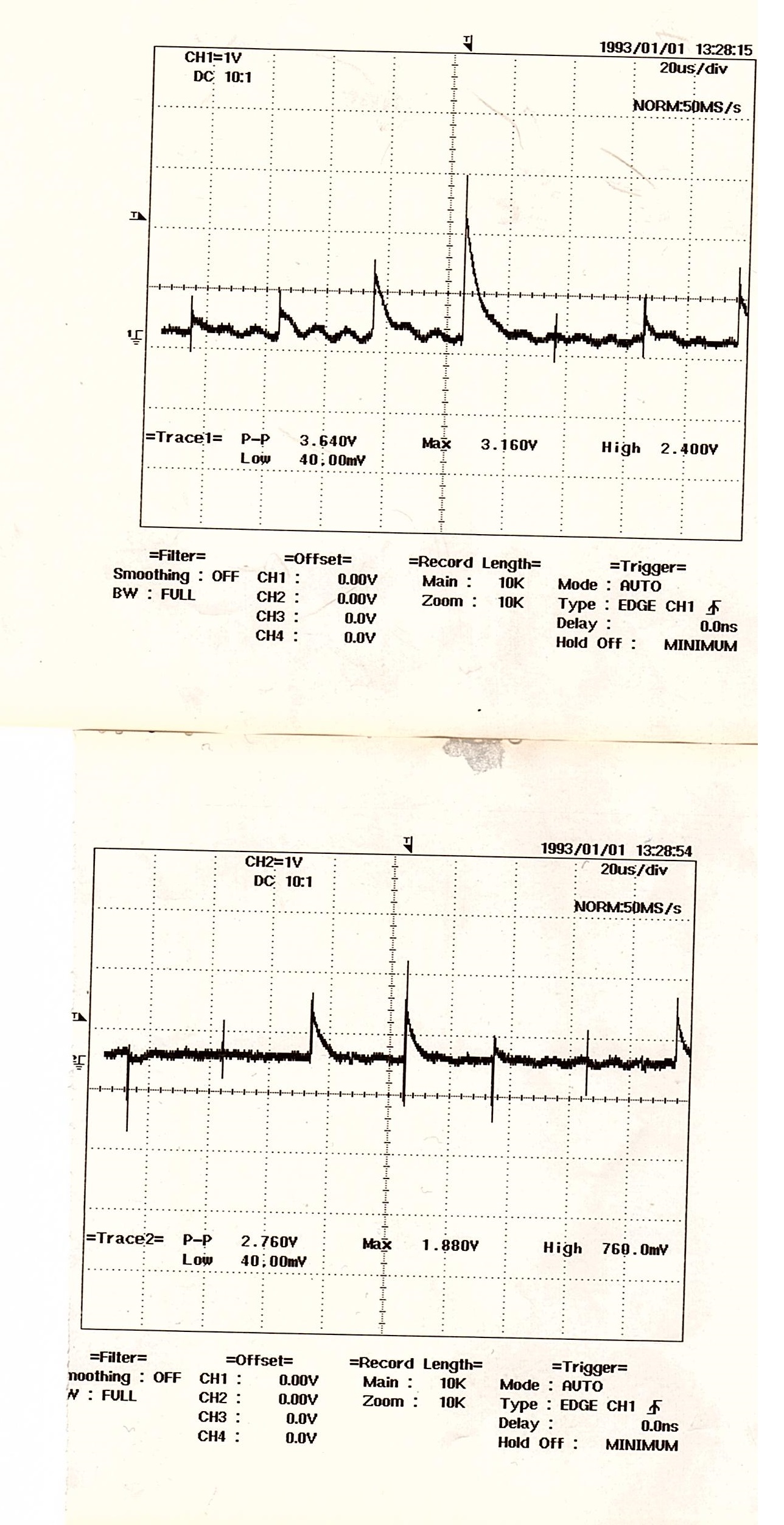
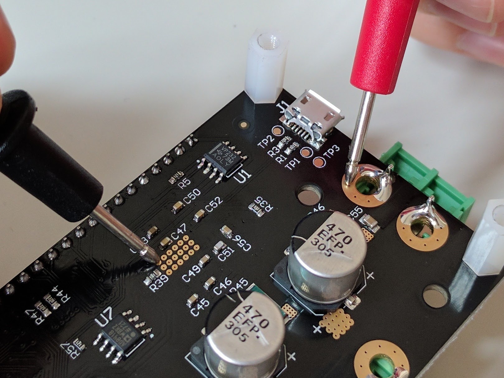
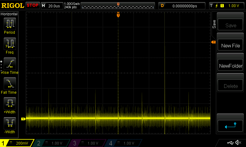
Seen below is the ground on J2, which is derived from the right side of the board (same “tap” as the microcontroller), measured against the GND on J3, derived from the left side:

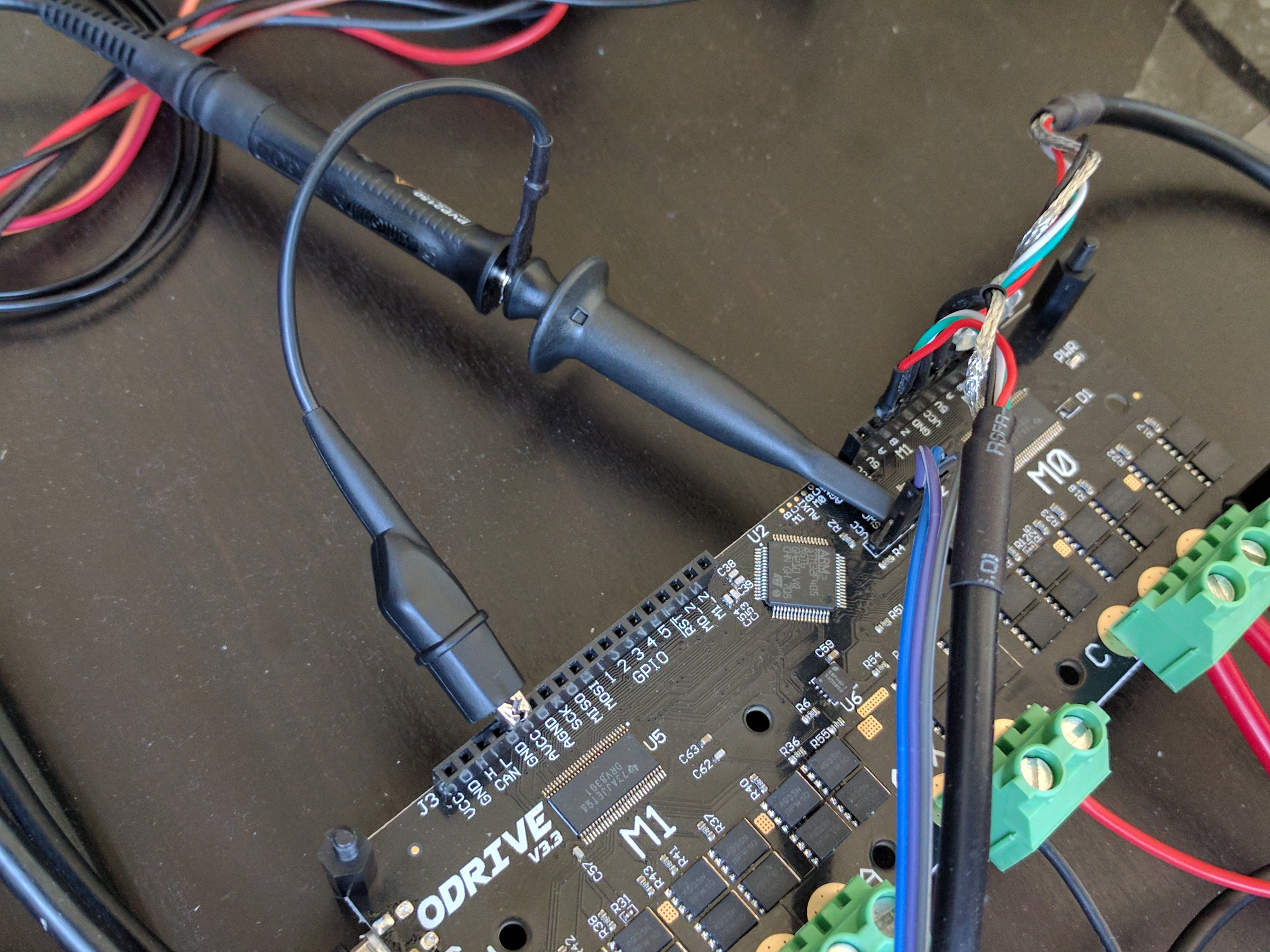
Measured with 10A motor current and at 12V bus voltage, we see spikes of 1.2V between the grounds.

Impact

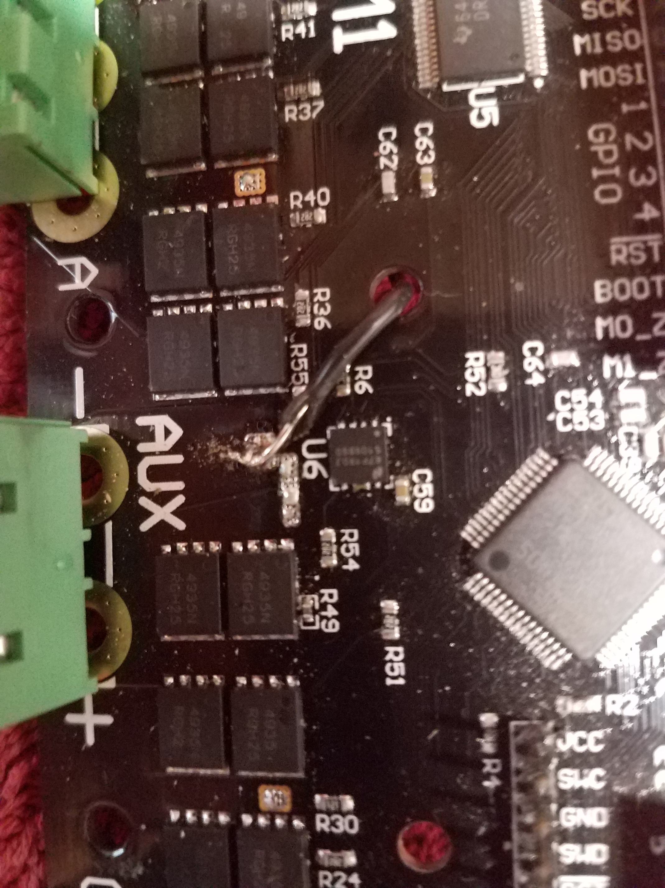
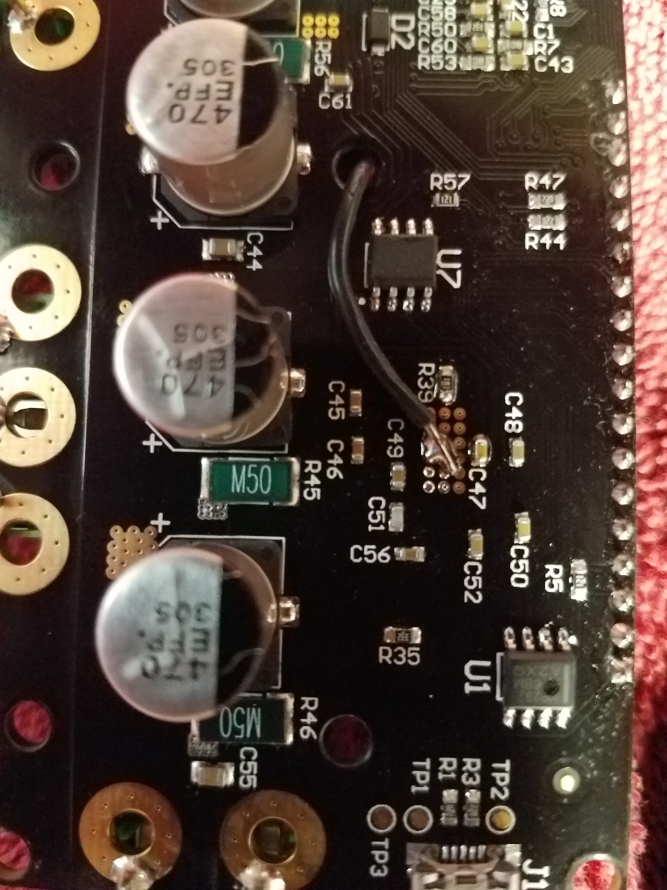
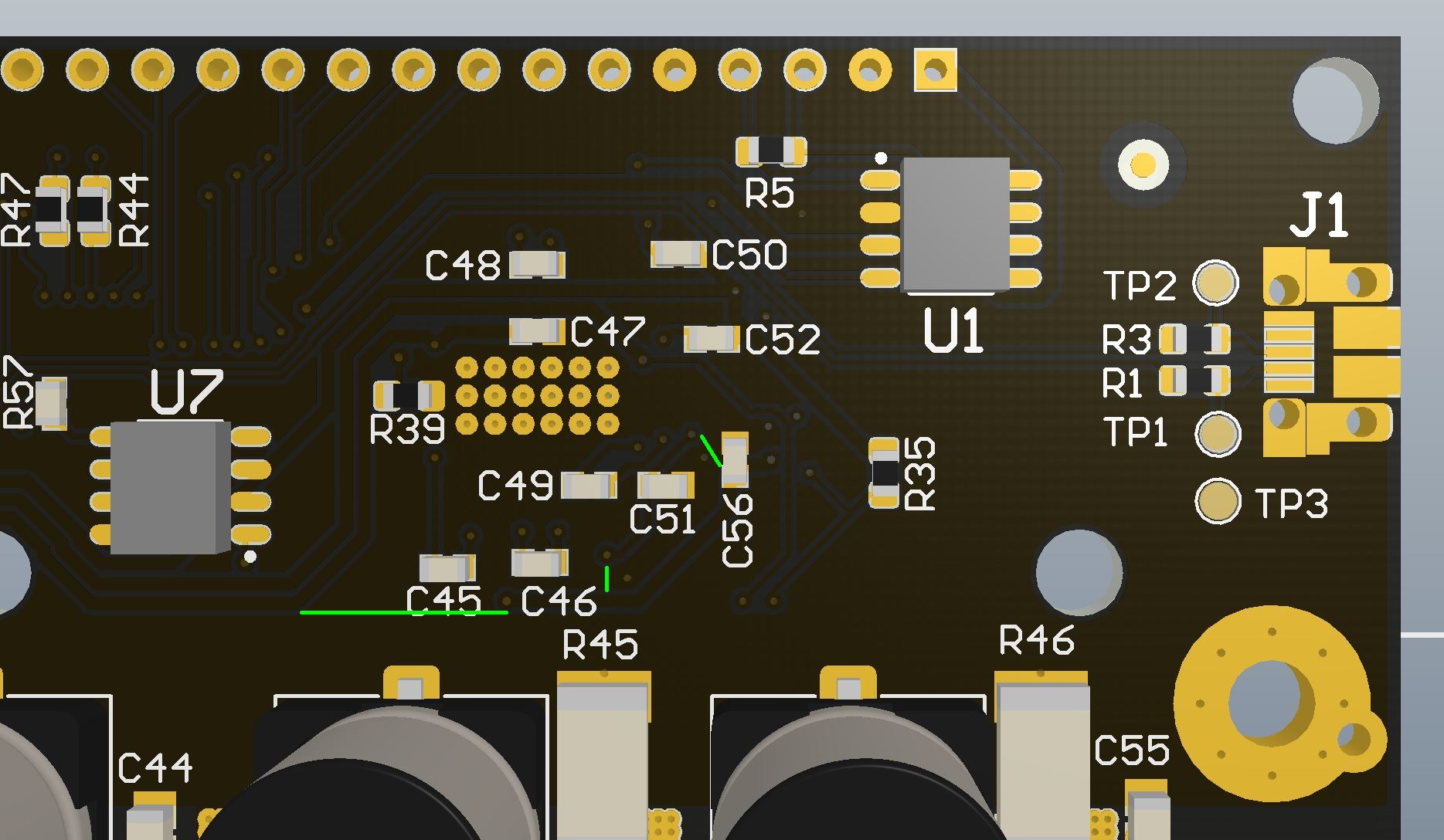
This means that you should not use the GND on J3, as that GND will have spikes on it with respect to the microcontroller GND. We have seen this cause spurious steps in the step/direction input. Please use J2’s GND when interfacing to the board: you can solder on some extra wires/pins, or splice a wire from the single connection.

As for other things affected, it is not yet clear how big of an impact this is, and what secondary issues this may be the root cause of. I will keep this thread updated when we have more info.

EDIT: See the confirmed impact and my suggested fix on this post.

Here is a printout from my scope ch1 is GPIO 3 to J2 gnd and ch2 is GPIO 1 to J2 gnd.
Sorry but my OSCOPE is old and it just has a floppy and a thermal printer. I would have used the floppy but I have no way to read a floppy anymore :). Hope this helps.

Just the scope on these pins, no wires or anything else plugged in?

That’s right. Scope only 2 probes 1 on each pin. I printed them separately for clarity. If you need anything else just let me know. The probe was on the gpio pin and the gnd clip was on the J2 gnd.

maybe this is a little easier to read

I did a mod and here is GPIO 1 using J3 gnd pin next to the can pins. Which was the worst one. This is acceptable as far as I can see. Looks pretty good. I will document the mod tomorrow<img <img

I have been testing my mod and I have not seen a stray step yet so, I am going to call it fixed. Here are 2 pictures to show What I did and where I did it. First a word of caution. The areas I picked are easy to find and don’t have a lot of components near them so that is good. The areas are not part pads but exposed plane areas. The bad thing about that is that there is a lot of copper that acts like a heat sink so it is hard to heat it up enough to get the solder to wet. (here is an explination https://www.quora.com/What-is-wetting-as-used-in-soldering-process ), The long and the short of it is that you have to get the copper hot enough to melt the solder and get a good connection. The dangerous part of that is if you heat it up to much you will melt the solder on the components that are near and they will fall off. I don’t want to scare anyone I just want you to be aware when doing this. Actually it could not be an easier fix.


It is best to use solid wire, it’s easier and you won’t get a stray piece of wire making a short and ruining your day.
Run it through the hole for the heatsink you see in the picture. If you plan on using a heatsink you can run the wire around the edge but that will make it longer which is not as good. I have been pushing my motors pretty hard and the board does not even get warm so you will probably never need a heat sink. Make sure your solder is shiny and you’re golden!

1 Like

Impact

I have confirmed that the following two bugs are fixed by fixing the grounding issue:

  • Spurious steps when using the J3 GND as reference for step signal (see thread).
  • M1 randomly glitches out (beeping, screetching, vibration).

The latter of the two is caused by the M1 gate driver receiving spurious switching signals.

The fix

The fix involves cutting the ground plane around the M1 gate driver in 3 places, and soldering a fix-wire to the GND on the back of a pin on J2. Tools required for the fix:

  • Good lighting
  • Utility knife blade, scalpel, or similar
  • Soldering iron
  • Piece of wire
  • Multimeter (continuity mode)
  • Superglue (or similar)
  • (Optional, recommended) Microscope, lupe, magnifying glass, or similar

Instructions:

  • Cut the ground plane in 3 places as shown in the images. Make sure to cut deep enough to get through all the copper.
  • Check with the multimeter on continuity mode that the M1 gate driver GND (the 6x3 array of vias) is no longer connected to the power negative (“DC -” on the ODrive). See picture.
  • Once you have checked that you have cut the connection, pour some super glue in the cuts, to make sure that some copper flake doesn’t make contact again.
  • Solder a 22 AWG or thicker wire from the GND pin on J2 to the back of the M1 gate thermal pads (the 6x3 array of vias). See picture. Note that you will need a lot of heat to solder to the thermal pads, I had to leave the iron on with a big solder blob for 10s before it would wet properly.

The fix in pictures

The following images illustrates the fix, are all views of the back of the board. Note that you can click on the pictures for higher resolution.


Cut along the green lines (3 cuts).


Cut along the green lines (3 cuts).


Cutting job done!


Check continuity here. These two points should no longer be connected after you have cut along the green lines as shown above. Note that in this picture I haven’t cut yet: but actually you should cut first before doing this measurement.


Solder fix-wire from GND of J2 to the thermal pads of M1 gate driver.

Question…

How will this effect future hardware iterations? (i.e. Fixing the board design?)

Going forward (v3.4 ondward), I will separate the digital ground from the power ground nets, and bring them together at a single point only.

This invalidates v3.3 then?

Well I’m doing the mod to all the v3.3’s before shipping them out, I’ll post pictures as soon as they are ready. But yeah I won’t manufacture any more v3.3’s after this, since this should be fixed.

After some more testing on my mod it is not as good as I thought. there were a few stray steps. I went ahead and did Oscars mod, I must say I like it. Works for me Oscar. Thanks!

1 Like

I attempted the fix suggested by Oskar and Bart today and everything worked as suggested. Note that depending on the exact placement of C56 you may need to cut down its left hand side a little in order to complete the cut as the capacitor on mine was overlapping the gnd plane a little. I did make one mistake where I accidentally cut the trace leading from the via right of C46 that leads to C51 when making the middle cut. However I managed to solder on an additional jumper to fix this problem and both motors are working without issue using the USB commands. Next I will be trying to get step/dir up and running.

Cheers.

1 Like

I tried using the step/dir functionality with the older 3.2 firmware and it does work but with very poor reliability. Despite having applied the ground plane fix I am still getting a lot of noise which is causing random steps when connections are made to GPIO 1 and 3. A 1kOhm pull down resistor connected from the GPIO pins to ground helped but did not eliminate the problem. Even with this noise I was able to have some control over the motors and was able to apply a square wave up to ~ 50 kHz (2 pulse per step) before control was lost.

In the video below (sorry, a bit shaky one handed) nothing is initially connected to the GPIO pins. I then connect the function generator (set to off) and you can see M0 begins to rotate freely from the noise placed on the pin. I then connect the 1kOhm resistor to ground the the situation improves but is not gone. Same story for M1. Still using M1 I supply a ~3V 10% duty cycle squre wave from ~ 1 to 50 kHz until the motor stalls at around 3000 RPM.

I have tried different power supplies at different voltages, braiding the wires to reduce interference and moving the drive further away from the motors. None of this seems to have had much impact.

I will try again once I can get the newer firmware working and hopefully that will help.

Quick question before going into too much detail: where is the ground for your signal generator output connected on the ODrive?

In the video it was connected to the large pad on the top side of the board next to the aux terminals. I have also tried connecting it to gnd on J2 but it made no difference.

Ok I see I did something wrong in that video now. Initially the function gen neg lead was not connected to ground and thats why it went wild when I connected the leads to the GPIO pins. I just tried again with the function gen ground connected first and then connecting the pull down resistor. Adding the pull down resistor now makes no difference.

However it is still unstable with the generator connected, but not producing a signal. Strangely, even just connecting my oscilloscope to the GPIO pins is enough to cause the motors to run randomly.

Just to verify, you tried this configuration?

Also, did you do this mod:


or this mod:

?

I just tried that exact configuration (Gnd on J2 and GPIO 1 connected to function gen) and unfortunately the problem remains. This is with your grounding issue fix applied (cutting PCB tracs, solder J2 gnd to M1 thermal pads).

I have also tried connecting to ground in a few other places but this did not make any difference. There is a possibility that there is something wrong with my function generator in the off position, but this does’t explain why I see random steps when also connecting my oscilloscope.

Oh and thanks for the quick reply!