Hi all,
I am working on a kinetic sculpture involving an odrive and hoverboard motors scavenged from a Segway Ninebot S Pro. The specific motors are https://more4motion.com/products/motor-assembly-for-segway-minipro
While configuring odrive to work with the motors I ran into issues with the hall sensors. I was getting an Error 16 for hall sensors configuration and the shadow_count never changes beyond a constant 0.
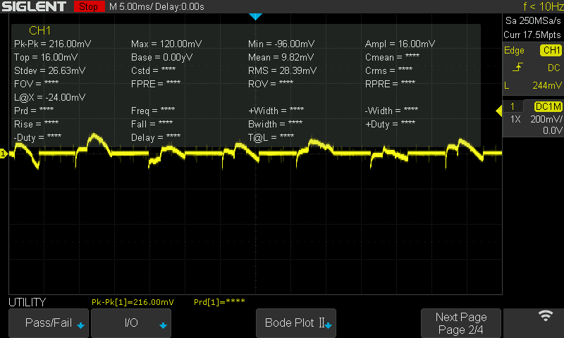
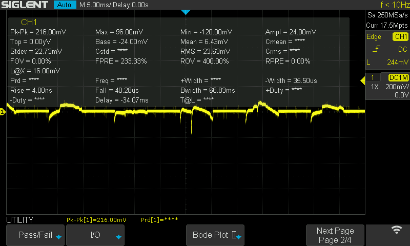
I pulled out my oscillioscope (Siglent SDS1104X-E) and did some readings on the hall sensors.
Im not getting anywhere close to a square wave or 5v on this sensor. Judging by the NineBot S Pro board, it is indeed a 5v hall sensor. Pinouts labeled as HA, HB, HC, 5V, GND.
First I connected 5V+ and - to the 5V and GND of the hall sensor, then I connected my scope probe to one of the hall sensor leads, and the ground clip to the GND (-5V).
Does this make sense to anyone? This is my first time working with hall sensors. If anyone has any ideas or suggestions I’d be eternally grateful.
Attached are two screenshots from my oscilloscope readout: