Hey folks,
I’m planning on building a rather large zoetrope-like thing, powered by a BLDC motor. I’ve got a bunch of questions about component selection, specification and system design, and was hoping to gather some input.
The platter for the zoetrope will be 1 m in diameter, and should weigh about 15 kg. The nominal speed is 20 rpm. According to my math, if I want to spin up to that speed from rest in 5 secs, I would need about 10 N-m of torque (ignoring all losses etc).
I don’t need positional control, and velocity control does need not to be terribly accurate (± 5% is probably OK), but I do need to know the actual current velocity accurately (say within 1%).
The system does need to be quiet (< 60 dB…not more than the volume of nearby conversation)
I’ll be controlling the overall system with a microcontroller.
The budget ideally less than $400 for motor and controller/driver.
My first question is about the torque required at startup: can I expect a BLDC motor to provide its rated torque from start (i.e. in the first revolution of the motor) or is some de-rating needed?
Second, what would be a good BLDC motor for this application? Is a direct drive motor of some type conceivable? Something akin to the direct-drive motors in some phono turntables?
Third, what kind of encoder should I use?
Fourth, what’s the recommended driver board for an application like this.
Finally, eager to hear any other comments/suggestion you might have.
Thanks!
Alden
Hi there! This is a super cool project!
Very trivial requirements, the only thing that I’d note as a potential issue is the noise constraint.
So, you need to accelerate at 0.066 turns/s^2. Assuming a “perfect” flywheel (e.g. all mass distributed on the rim of a 1m diameter disc, which is the worst case moment of inertia), the moment of inertia should be about 3.75 kg-m^2. My math shows you should only need about 1.57 Nm of torque for that initial spinup.
The ODrive S1 + M8325s kit ($329) will be able to peak at around 5 Nm, though the fact that it’s an outrunner may lead to a bit of noise, though I’d imagine way less than 60dB at low speeds. However, that’ll be a nice all-in-one solution that’ll work great in a direct drive setup.
Alternatively, for a bit tighter speed sensing and likely quieter overall solution, you could use:
- ODrive S1 ($149)
- S1 Enclosure ($19)
- 5312s motor ($59)
- 16384 CPR RS485 encoder ($59)
- Motor mounting plate ($12)
- USB isolator ($16)
That’s $314 total, and the 5312s will be able to peak at about ~1.5Nm for the initial spinup (so would be fine for direct drive), though would benefit from a simple 1:2 belt drive. You’d also be able to mount the S1 separately from the motor/encoder package, in case you’re space constrained.
Finally, you could use something like a Cubemars GL60 KV25 (~$130 including shipping) with an ODrive Micro ($99) and some 3D printing to mount the Micro onto the GL60 and fixture an encoder magnet so the Micro can control the motor – I have a little example reference design for this I can show if you DM me. That’ll be tiny and quiet, though likely only able to put out about ~1Nm of torque, if a slightly slower spinup is okay.
Overall, if I was designing this, I’d probably just get the S1 + M8325s kit and use it direct drive  probably the easiest overall solution.
Hi Solomon,
Thanks so much for the detailed help. Much appreciated!
Looks like made an error in my math. I’m assuming that the disk is uniform, so I = 1/2 * M * R^2, which gives me about 1.9 kg-m^2. In any event, nice to have some additional margin of course.
I like the simple approach, so I’ll just go with the S1 + M8325.
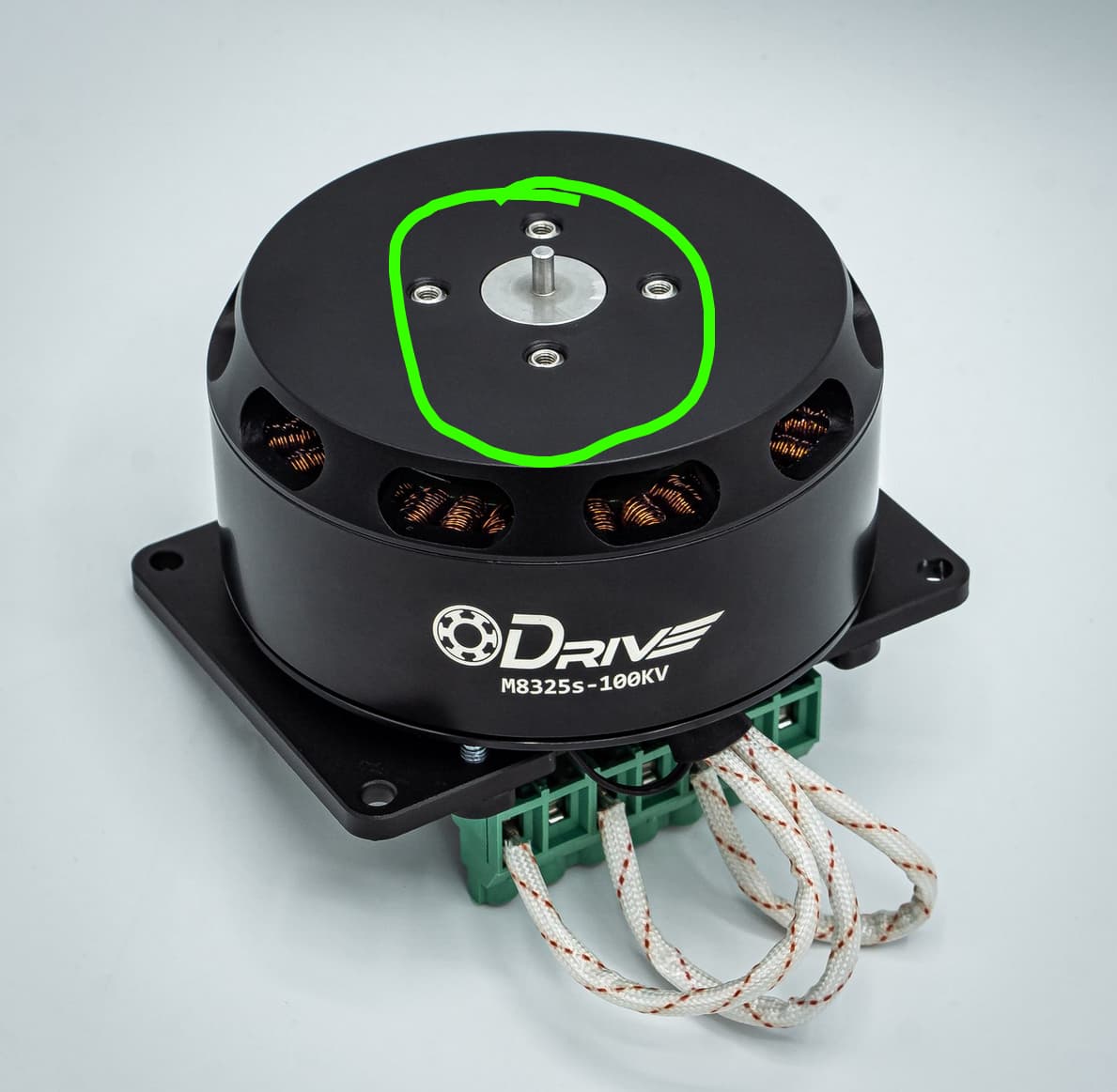
One quick question about the motor: from the CAD data it looks like it’s got a (tiny!) 3 x 6 mm (D x H) output shaft. Is that right? I’m a little concerned about coupling a 15 kg mass to that tiny shaft. Any thoughts or suggestions?
Thanks again.
There’s four bolt holes on the front of the motor, the small shaft is just for centering
Ah, got it. Didn’t realize the top surface rotated.
Thanks again Solomon!
No worries, let me know if there’s any other way I can help!
Hey Solomon,
Is there a spec for the max axial load for that motor? Now that I have it in had, at seems like it might be beefy enough to mount the platter directly.
Any thoughts or info?
Thanks again.
I’ll check with the team! This’ll be axial load, correct?
Hey @solomondg, I don’t suppose you’ve got any info to share?
Thanks!
Hi! Sorry, it doesn’t look like we have this information. I think it’s definitely worth giving a shot – it’s based off a drone motor so it’ll be designed for 10-20KG of thrust from a propellor. If you want to be paranoid you can add a thrust bearing, but I think it’s worth trying.
Ok, thanks for asking anyway Solomon. Appreciate it. I’ll give it a try!
Hey @solomondg,
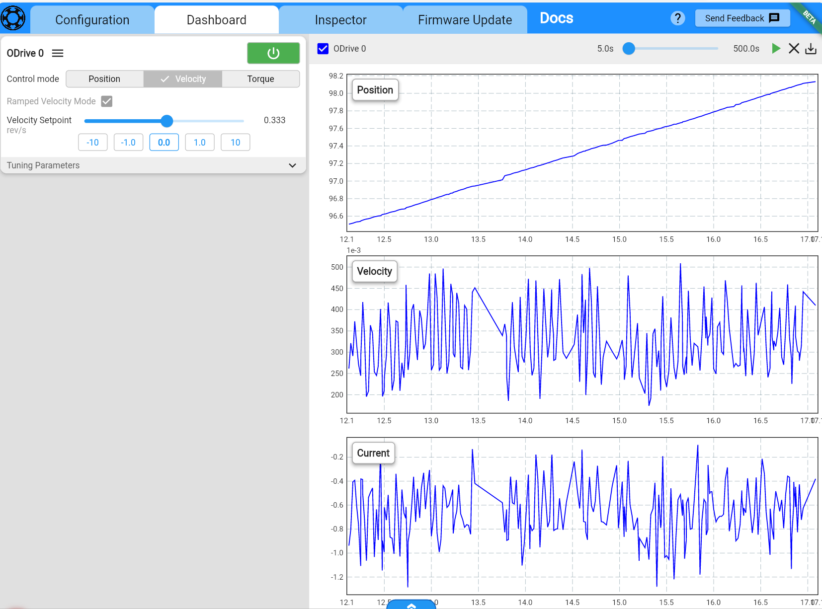
I’ve got my parts assembled, configured, etc. However, I’m seeing quite a bit more velocity error than I would like. If I specify 1/3 rev/sec in the dashboard, the result varies between .2 and .5 rev/sec (about 50% relative, error).
Notes:
- No load is attached to the motor
- Power is a linear power supply set to 20V (can provide up to 5A)
- Power config settings as shown below
- Tried Ramped Velocity and Velocity control modes with similar results
I noticed that if I set the target velocity to 3 rev/s, the relative error is much lower (around ± 2%) and the absolute error is also a bit lower (around ± 0.06 rev/sec).
Is there something I can do to reduce velocity error while running at 1/3 rev/sec? Or will I need a reduction to get the desired velocity accuracy.
Thanks very much.
Hi! Did you tune your PI gains? And/or do anticogging calibration?
Also - got bearing information they’re 6802zz Item # 6802ZZ, 0.5906 Inch (in) Bore Diameter (d) Shielded Extra Thin Metric Ball Bearing On SPB USA
Hey @solomondg,
I just tried to tuning the P and I gains for V according to the procedure in the docs. (I’m assuming set positional gains aren’t relevant since I’m using velocity control mode). I ended up with Vp = 1 and Vi = 1.7.
Unfortunately, I only achieved very modest gains in velocity accuracy (~ 10 %).
The avg angular error works out to only around 1.3 deg. This sounds reasonable enough, but given a 1m disc diameter, this implies about 10mm of positional error for the edge of the disc.
Maybe another alternative is to not worry about perfectly accurate speed and simply flash the strobe when a target angular position is reached. I’d need to poll the position rather frequently though. Is there a max polling rate that can be achieved over UART or CAN?
I looked at the anticogging docs, but got stuck on a few points. Given my config (with built-in encoder, no limit switch, etc), it sounds like I should be looking at Custom User Reference Frame, correct? If so, I’m unclear on how to set “odrv0.axis0.pos_estimate = angle on every start”. Is that possible from within the web UI? Or would I need to do that via the command line tool or over the UART/CAN interface?
Finally, thanks for the info on the bearing. I couldn’t immediately figure out how to determine the max axial load from the information provided there, but I concluded mounting the load directly to the motor is a bad idea for other reasons, so not important any more.
Thanks again for all the help. Much appreciated!
Hi! I agree that flashing based on the angular position makes sense – UART will likely support a few hundred Hz up to a kHz, CAN can do a kHz easily – and with periodic messages, you just have to listen.
With anticogging, you’d want the Absolute Encoder Reference Frame, since you’re using an absolute encoder.
Let me know how else I can help!