sine wave commutation suffers from reduced power load compared to trapezoidal since the average current is lower. So I’d like to know how much will my RPM reduce compared to an ordinary ESC using trapezoidal commutation? I was thinking of 1st, calculating the coefficient of friction k using the ordinary ESC
airFrictionTorque = k * angularVelocity = motorTorque
then derate by a constant factor for sine. Does sine reduce the average current (hence torque) by some magic percent for all RPMs, or is it more complicated?
So far I’m assuming the sine has the same peak voltage as a trapezoid. So if the torque load is tiny, then the top RPM should be unaffected, just take longer to accelerate.
But then I saw this post:
It says the peak voltage is reduced to 87% of bus voltage? My power source is 12V, so that would be pretty bad.
The obvious solution is to get a higher KV motor. I also read about hybrid sine commutation for low RPMs and then switching to trapezoidal at high RPMs. Is that any good?
Sorry I couldn’t find the reference in that thread, and also I don’t understand what “power load” is in this context? Can you please explain and/or link to the exact post in that thread?
Usually you get aerydynamic drag being the square of velocity. I don’t know why you need to derate for sine: sine commutation produces torque more efficiently than trapezoidal commutation.
If a reduction in speed of 10% is a big problem, then your design is too marginal anyway: yes just get a larger kv motor (and a physically larger motor if overheating is a problem).
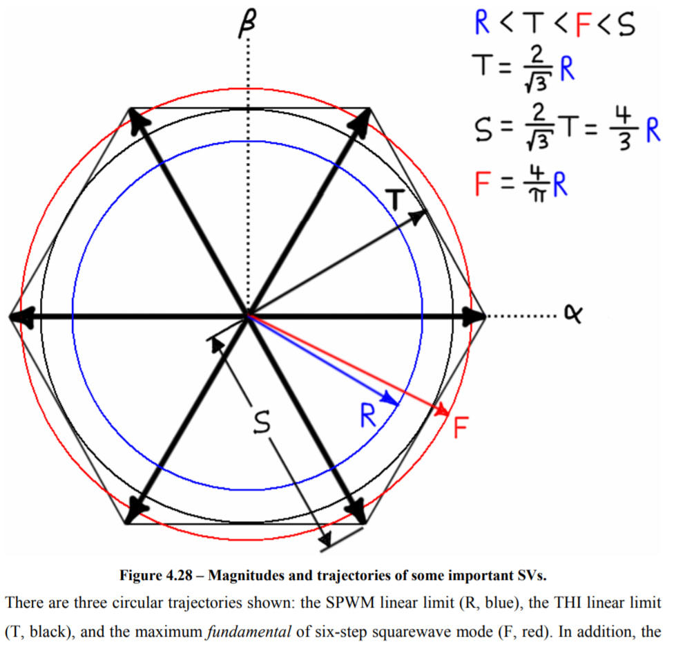
For reference about the base speed of different commutation methods, my favorite is this thesis. It conveniently includes this graphic to compare achievable voltage magnitudes of some different strategies:
So is the formula for no-load speed KV * bus voltage * sqrt(3) / 2 * 0.8 ?
So if I want 5000 RPM with O-drive using 12V, I would need a 600 KV motor instead of 420 KV if using an ordinary ESC.
When I claimed sine commutation has reduced power for a given bus voltage, I was quoting mjsas on rcroups.
The problem is with sin wave drive is that a higher voltage battery is needed to get the same power
It makes some sense because clearly, trapezoidal commutation (a square wave with 2/3 duty cycle) is putting more energy into the stator windings. A sine wave has a 1/sqrt(2) = 0.707 RMS average while a 2/3 duty cycle square wave will have sqrt(2/3) = 0.816 RMS average.
But I don’t know how that extra electrical power translates into actual shaft power. I think some of it will be wasted from generating a stator field parallel to the rotor field, which generates no torque.
SVM looks interesting. It seems very similar to micro stepping, except with 3 instead of 2 phases. How many “micro steps” does O-drive do?