First time attempting to use an ODrive (V3.6, 56V), and unfortunately it hasn’t been easy. I’m trying to drive a geared hub motor - Bafang’s G311 (more stats) with 30:1 gearing and hall effect sensors. I’ve changed some of the parameters to suit this motor, and have had no problem running the full calibration sequence (the motor spins forward 1/30th of a turn and then stops). However, when the motor stops and I call dump_errors(odrv0), I receive just one error: ERROR_ENCODER_ILLEGAL_HALL_STATE.
Thereafter, the motor is unresponsive in CONTROL_MODE_CLOSED_LOOP_CONTROL. I am able to calibrate the motor as many times as I want, but never to put it into any other control mode, or do anything else.
I’ve seen the other posts on this forum relating to ERROR_ENCODER_ILLEGAL_HALL_STATE and checked for some common issues that may cause this problem. I first checked with a multimeter to see if any of the hall effect outputs are stuck high or low, but all (A,B,Z) reliably shift from low (~0.01 V) to high (~3.05 V) as the motor spins, and although I can’t really turn it one revolution, because of the gearing, I haven’t been able to find any point at all where either all 3 are high or all are low. Since this seems to be the only (or primary?) condition that results in this error, I’m really struggling to solve this so that the motor can be run. If anyone else has experienced this issue, or has any advice on how to get the board and motor working, it would be greatly appreciated!
Please can you check the value of encoder.hall_state - it should change value as you manually turn the motor. If it is stuck at zero then something is wrong.
You could even try the liveplotter. Edit tools/odrivetool and change this section
        # If you want to plot different values, change them here.
        # You can plot any number of values concurrently.
        cancellation_token = start_liveplotter(lambda: [
            my_odrive.axis0.encoder.hall_state
        ])
If you find that it is cycling between all six states correctly but only sometimes it jumps to an illegal state (0 or 7) then probably you have electromagnetic noise causing interference on the encoder wires.
You can try using a ferrite ring from the shop to reduce the noise emitted from the motor wires, and/or adding a 22nF capacitor to GND on each of the A,B,Z pins.
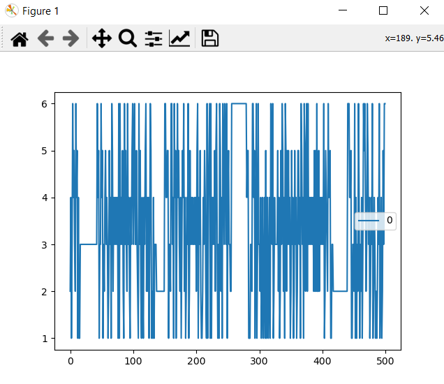
Towen, thanks for the help! However, it seems to change value fine. Because it’s a geared motor, it’s really hard to spin at a speed slow enough to accurately capture the order in which it passes through the steps, but I spun it manually for several minutes with the liveplotter going and saw only what’s shown in the screenshot above ^^, losts of 1-6 states but never a 0 or 7. (consistent with what I measured at the hall effect pins) Any ideas what could be causing this error when it never actually seems to go to an illegal hall state?
Is it possible for you to run the same plot while you try to run the motor? e.g. send a command over UART or CAN to go to the calibration sequence?
Or set axis.config.startup_full_calibration_sequence = True and start the liveplotter immediately when you turn on the ODrive.
This suggests to me that you -are- having problems in calibration. The motor should move forwards and then backwards. If it moves forwards and stops, then the calibration has failed. Usually because of a CPR_POLEPAIRS_MISMATCH but in your case I strongly suspect that electromagnetic noise from the motor wires is interfering with the sensor wires, causing ILLEGAL_HALL_STATE whenever the phase PWM is enabled.
To prove this, you could try reducing the supply voltage. The amount of noise can go with the square of DC Bus voltage, so you might not have to reduce it by much to see a difference.
Please try the ferrite ring (common-mode choke) on the motor wires, and the capacitors on the sensor wires. That should be plenty enough to run at full voltage.
This could be a firmware issue and nothing to do with noise. There are some known bugs due to config compatibility between firmware versions. If you have recently upgraded from 0.5.1 to 0.5.2 without erasing your config, then apparently this can cause ILLEGAL_HALL_STATE errors.
Can you add encoder.shadow_count to your liveplotter?
If it stays at 0 while the Hall states change, then it’s a firmware bug.
Try backing up and erasing your config.
Very interesting - I seem to be having the symptoms of both problems at once! Running the liveplotter during the calibration sequence does show that the hall state somtimes jumps to 7 or 0 (which was never seen manually turning the motor), AND the encoder.shadow_count does remain continuously at 0 when the motor calibrates and the hall state changes. The odd thing though is that I built the config entirely after upgrading to 0.5.2, so that makes me think it may just be the EMI. Does this make sense?
Also, just for due diligence, tried re-installing 0.5.2 and making a new config file - same problem: mostly normal hall states during calibration but the occasional jump to 0 or 7. I’ve ordered the ferrite ring, and will set that up on the motor phase wires as soon as I get it. I’ll try that, as well as 3 22 nF resistors between the A, B, and Z hall inputs and the hall ground. Hopefully that works.
Yes it sounds like it is indeed just the EMI problem then. I’m sure those measures will fix it.
it is weird about the shadow_count not updating though. What about pos_estimate?
Im having a similar issue with illegal hall state (after the odrivetool dfu update), and ferrites didnt do the trick. Any other ideas you guys might have?
Same issue here; ENCODER_ERROR_ILLEGAL_HALL_STATE during:
odrv0.axis0.requested_state = AXIS_STATE_FULL_CALIBRATION_SEQUENCE
Motor starts turning forward, but then stops with this error.
Odrive v3.6, odrivetool v0.5.4, ferrite added, 22nF soldered on board at Hall sensors inputs, ‘encoder.hall_state’, and ‘encoder.shadow_count’ do remain continuously at 0 if I rotate the motor by hand (while I can see the Hall sensors change at my external oscilloscope).
I tried the same channel of this odrive board on a hoverboard motor, and that worked fine.
I have got the shadow_count increasing now. But still: ENCODER_ERROR_ILLEGAL_HALL_STATE
The statement “encoder.config.ignore_illegal_hall_state = True”, before starting calibration, doesn’t help.
Are all three Halls working? Maybe one sensor is inverted? You should see six states: 001:1, 011:3, 010:2, 110:6, 100:4, 101:5 (in that kind of order I think but I can’t be sure on that), and you should never see 111:7, or 000:0
Can you use the liveplotter to display the hall_state?
(you need to edit tools/odrivetool and look for the liveplotter bit where it adds the signals, should be fairly self explanatory)
Yes, the Hall sensors are working properly (with six states, not 000 and 111).
I progressed a bit further; when I do the three calibrations separately, I don’t get errors. And I discovered that ignore_illegal_hall_state only works in closed loop control, not during calibration. I have had a working torque control once, but now only velocity control.
Playing a bit further (and resetting, and fresh calibrating the board, several times) I discovered that torque_mode isn’t working at all, but switching from torque to velocity_mode enables both input_vel, and input_torque. So my odrive acts properly on both input settings simultaneously if in CONTROL_MODE_VELOCITY_CONTROL (after first trying and failing CONTROL_MODE_TORQUE_CONTROL). Looks like a bug to me.
It’s at least partly expected behaviour to respond to input_torque in velocity mode.
The input_torque is taken as a “feedforward” term and added to the output of the velocity controller. So if for example you happen to know approximately how much torque you need to drive at a given speed, you can supply it as a feedforward, and it will increase the control performance.
That said, if you set velocity mode, with input_vel=0 and input_torque initially 0, and you then set input_torque to some value, I would expect it to move a bit, then stop, and move back.
The reason for this is because the velocity controller is trying to control the velocity at 0, and so it applies a torque proportional to velocity in the opposite direction of motion, like friction. But by default, there is also some integral action, and the integrator will apply a torque proportional to the area under the velocity curve, so that it also reaches 0.
These torques are added to your feedforward input_torque, but eventually the integral term will grow such that it all cancels out.
I am not experiencing any wind-up effects. But I did:
“odrv0.axis0.controller.config.vel_integrator_gain = 0”
maybe that makes a difference.
control_mode = VELOCITY or TORQUE doesn’t make any difference; I can set input_vel and input_torque, and my motor acts accordingly to both at the same time. It might not be the expected behaviour, but it is good enough for me at this moment.