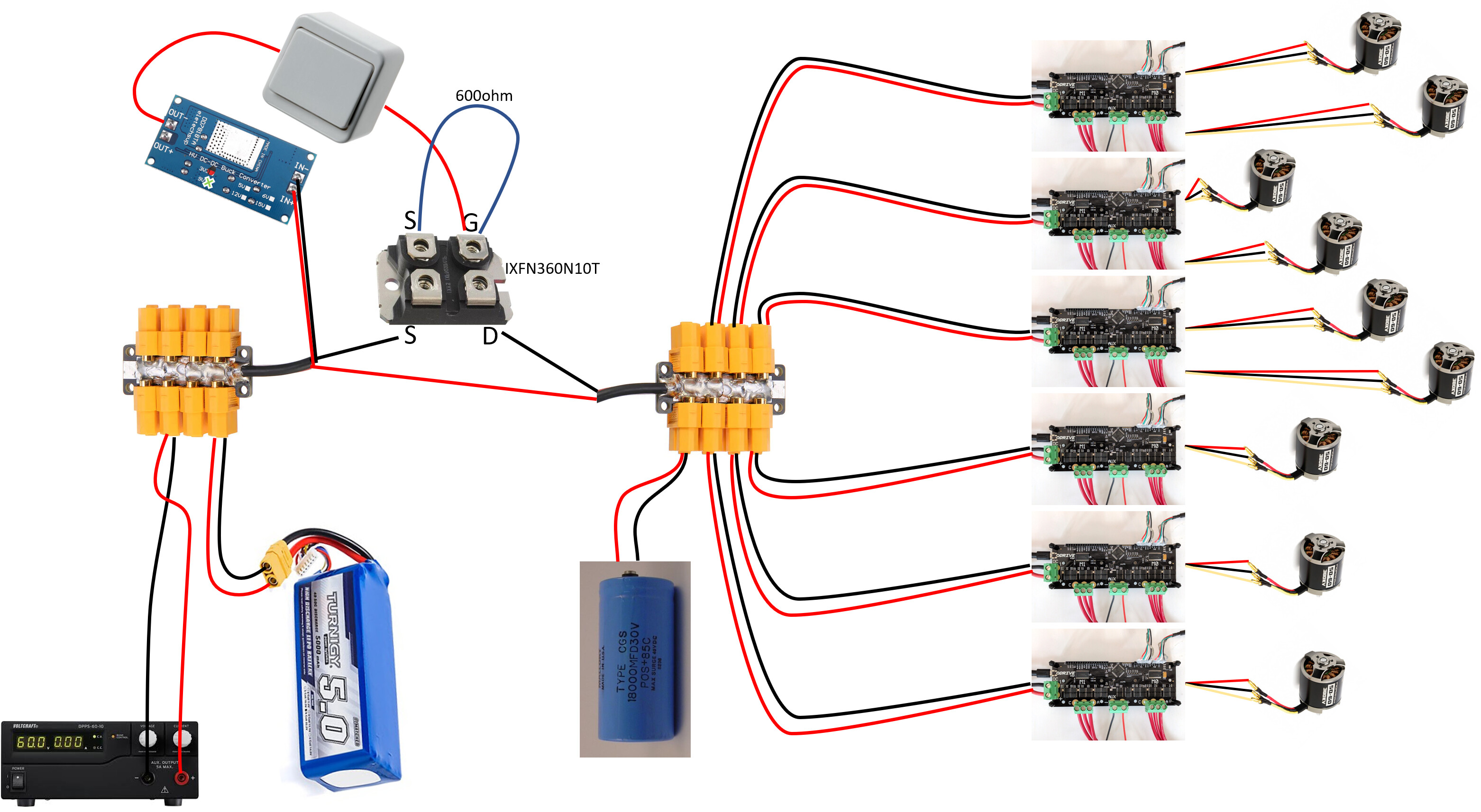
It is time to improve the power delivery side of my setup, and I’m looking for some advice. I added an emergency stop button to my setup. It works nicely, but shorted out recently, I believe due to inrush currents caused by the high-capacitance of my setup.
I was wondering if anybody had advice on how I can improve my setup? I don’t have any EE experience, so I’m looking for simple/discreet solutions, no IC’s or custom PCB’s.
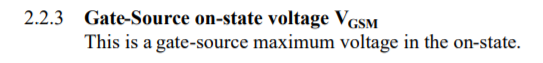
Should I focus on limiting inrush currents, or are there other more glaring problems? The large capacitor (18000uF) is a safety risk, and I might remove it at a later date, but for now it helps smooth out large spikes in power demand.
One of the things i will be adding is 30A/40A fuses on the power lines of my ODrives. I might try adding one on my battery too, though I haven’t really looked into that yet.
I frequently check the balance on my lipo, and always disconnect it after use.
Your e-stop button shorted out?
That’s the one thing they should never do… They are normally forced contacts… But they are not meant for high currents, so it may have welded.
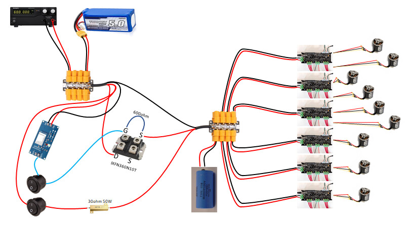
I would avoid driving a MOSFET with a switch. It can be done ofc, but you never want to leave the gate floating - it should be tied to 0V or VSS+9V at all times - That’s a N-channel mosfet, so it won’t work unless your dc-dc converter is isolated and is referenced from the positive side of the battery…
I’d recommend a relay contactor e.g. a KILOVAC, or else a “solid state contactor” which is just a MOSFET + driver circuit in an integrated opto-isolated package. You drive it as you would an LED.
But if it’s just a manual switch you need and not a real e-stop, then a battery isolator switch is a lot cheaper.
Yeah, inrush currents are to be avoided. They can damage the ODrive in extreme cases.
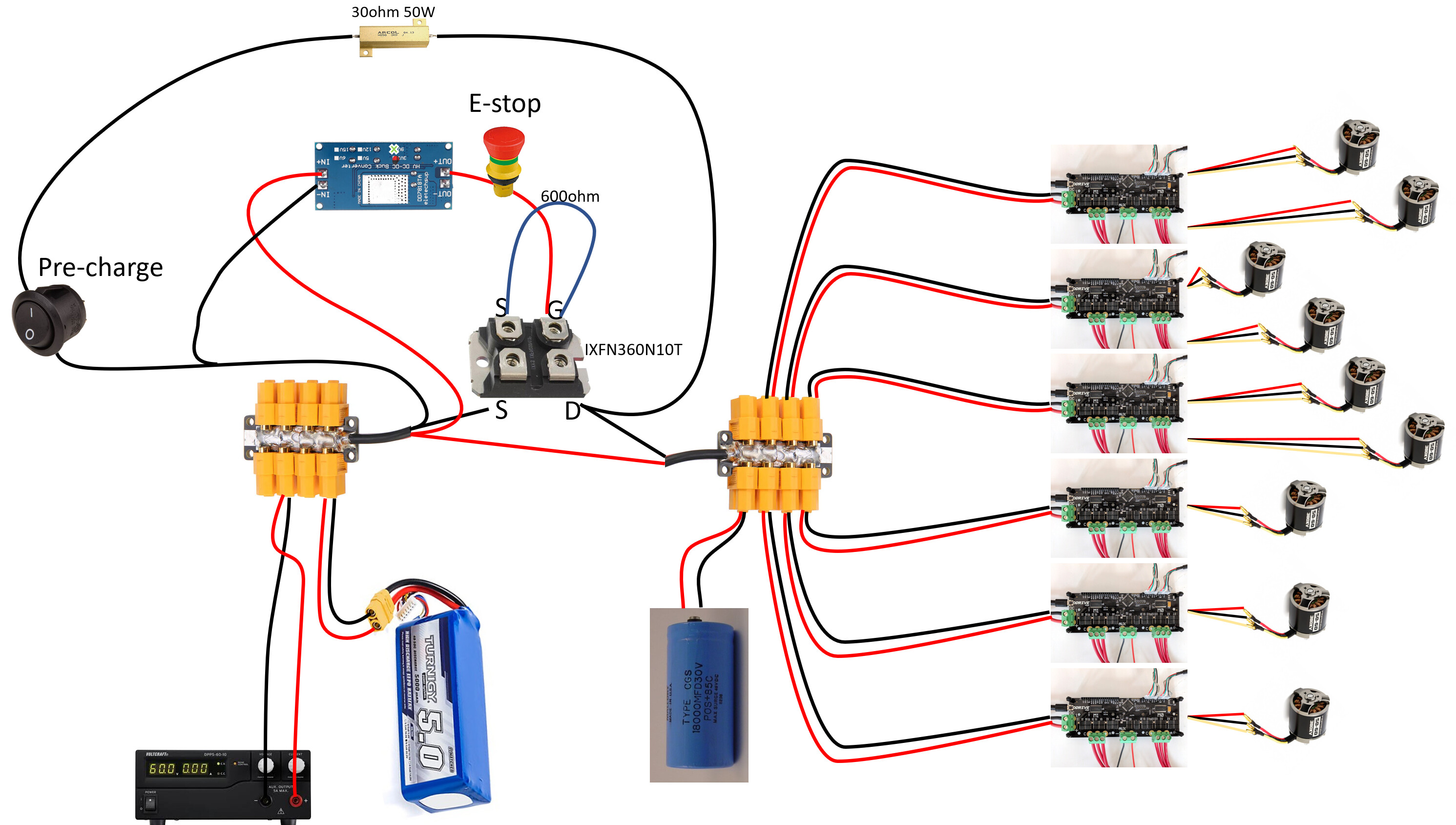
You could switch in a resistor across the relay as a simple manual pre-charge to avoid inrush - by the same token you could put the same resistor to GND when off to discharge your capacitor.
I have a 100A fuse permanently soldered in line with my battery which is enough to discharge it at 4C i.e. from 100% to 0 in 15 minutes flat. I can’t imagine needing to go higher than that, and in any case I am using a 90A xt90-s connector. For me, the anti-spark connector serves as a disconnect and a pre-charge.
I don’t have a machine big enough to need a “real” e-stop, but if I did, I would want one that disables the high-side drives on the ODrive without resetting the software, and lets it pull the low sides low to stop the motors immediately rather than letting them coast. It doesn’t exist yet for ODrive, but that’s what industrial drives do.
Speaking of machines big enough to need emergency stop buttons, what in Bob’s name are you doing that needs 6 ODrives and lots of power?
Anything with big capacitors like that should have a “soft start” or “pre-charge” circuit to keep the inrush currents low. This is basically just a relay that charges the cap through a big resistor, then eventually you connect the main power and skip the precharge relay
Yeah, scared me too. Luckily, I didn’t need it when it happened.
I made a mistake in the drawing, the gate is driven by the + side of the buck-converter. It has a pull-down resistor. I’ll connect the - output of the buck-converter to the - input, I assumed the device already does this internally. In which situation am I at risk of a floating gate?
Looks like what I need. Except pretty expensive, and I’m worried about weight and size. Especially if I move up from 28V to 48V. The solid state contactor is nice, I tried finding one with sufficient amp rating, but wasn’t very successful. that’s why I choose this MOSFET.
I initially considered one of these, but I want the switch +2 meters away from the setup. That would not be practical with more than 2 amps running through the parallel wires.
I might add one specifically to the capacitor. Currently the ODrives draw enough current in idle to pull the power down within maybe half a second.
Yeah, I have the same plug on my battery. I will be adding a fuse. Probably somewhere in the 50-100A range.
I considered adding an NTC thermistor, but i prefer the robustness and simplicity of a pre-charge resistor. Which you both advise.
What I’m looking into at the moment is a three way switch of some kind. 0 - off, 1 - precharge through a 30 ohm resistor (~1 amp), 2 - open MOSFET. I’m having a tough time finding a suitable toggle switch though. Preferably a push-button, that unlocks from state 0 through 1 to 2, and when pressed goes straight to 0 again. Any suggestions?
Yeah, that would be a lot nicer. Then I wouldn’t have to re-calibrate all the time. And make it easier to read out errors, when something has gone wrong.
Getting my robot to walk, obviously! Haha. I’ll make some videos when I feel safe powering it up again.
One big issue with this is that you are interrupting the negative side (of couurse, because you have an N-channel mosfet without a boost converter). This means that your USB/UART/CAN comms grounds will float up to your battery voltage when you open the mosfet. You don’t want the current to bypass your mosfet and blow up your controller (e.g. raspbery Pi) instead!
Sorry, hadn’t noticed that till now.
Isolated comms may “work” but it’s still very bad practice. A short between one of your encoders’ grounds and chassis ground for example could mean that the encoder + drive goes up in smoke as soon as the e-stop is pressed.
Hmmmm. Thanks a lot for pointing that out. You’re right, I really don’t want my system to have a differential to ground when it is “off”. Lots of things could go very wrong.
So if I get a boost converter that will take my 27.5V input and convert it to 37.5V output, I should be able to drive my n-channel MOSFET on the positive side right? Something like this. Though I’m not sure what would happen if the ODrives drew enough current to cause a voltage dip. I don’t suppose I can connect the output - of a boost converter to the input +?
Other options being:
An opto-isolated (P-channel) relay like you suggested, though they seem quite expensive and require more cooling.
Some boost converters are isolated/floating, so you can connect the output to anything, including the input +, but most are not.
I have also tried using a 9V battery referenced to VBus before, and ended up with a lot of smoke. Not entirely sure why but I abandoned that approach and used proper gate drive ICs for all my mosfets after that.
I would suggest #2 - although you need to be careful about arcing with a relay designed for 12V DC. I think the reason KILOVAC units are expensive and rated to 900V DC, is because they are evacuated, ie sealed with vacuum inside filled with Nitrogen to prevent ionisation/arcing.
They are less expensive than your P-mosfet though.
(the 12V is the coil, not the contacts - the smallest one is 900V/100A and weighs 190g so you don’t need a bigger one )
If you do use an automotive relay, you could put a reverse diode across the contacts (you want one for the coil anyway) which will prevent arcing when opening.
Hey all I just wanted to share my thoughts. I added e-stop functionality to the Odrive firmware and it has been working very well for me for over a year now it instantly disables the motors when I hit the e-stop by throwing an error state. I maintain the serial connection to the odrives so it is easy to clear errors after resetting the e-stop.
My firmware branch is old and a bit of a hack, but the change is very simple if you wanted to add it to the latest branch:
That change requires that Pin 8 is connected to 3.3v (or otherwise reads logic high) or everything will shut off. On it’s own it is an effective and zero cost way to make an e-stop work for your odrive.
As an additional measure, I made a carrier board that plugs in to the odrive header. On that carrier I have a hardware watchdog chip. The watchdog chip asserts pin 8 high when one of its inputs is toggling every 100 milliseconds or faster, otherwise it goes low and activates the e-stop. I communicate with my odrives from python on a raspberry pi, and in my motor control code I constantly toggle one of the raspberry pi pins. That pin goes to a mosfet which is fed from 5 volts. That 5 volt line is where I put my e-stop switch. When the moseft is getting 5v power, it outputs the square wave which goes to all my odrives. If the python code on the raspberry pi locks up, the square wave stops and the hardware watchdog on each odrive will send them in to e-stopped mode. And if I hit the physical e-stop, it cuts the 5 volts to the mosfet and kills power to the square wave.
We are about to open source our motherboard, which has these features mostly on it, designed in KiCAD.
But you can see my odrive interface board with the watchdog on it here:
Note that I am using an ethernet jack for RS-485 commsl. It is a great option as RS-485 has the same physical spec as CAN bus but with the ease and full odrive interface of normal serial.
I found that those chips don’t quite like to turn on the odrive. I think the inrush current sets them to protective mode. But a so far workable solution has been to toggle them on and off with a millisecond delay 100 times or so, then keep them on. That works every time. In the next rev I will add one of them with a separate toggle line and a current limiting resistor, as I feel that rapidly sending them in to reset may reduce their life. But it’s been working for 10 months or so so far.
The LTC4368 is the perfect IC for this - you say you don’t have any EE experience, but this is probably worth throwing a couple bucks at someone to get a PCB designed, especially if it’ll save you a blown Odrive or two.
I want to try sticking to the n-channel MOSFET for now. I can see the advantages of using the KILOVAC though. When I burn through this MOSFET I’ll order one.
Good point, I had forgotten about using a software e-stop. It would really improve my workflow, so I will be adding this later.
I looked into it, but had already ordered everything I need for the setup I’m using now. Although it would simplify the circuit further, which I find attractive.
I’m kind of confused though, will the MOSFET really be able to interrupt the inrush currents? They are a lot higher than it’s maximum rating. I don’t think the MOSFET shorted out because of insufficient cooling.
What kind of boost converter board do you have there? Have you checked that it is a floating output (you also need to connect the negative output to the positive input for your MOSFET to work)
As for inrush, that MOSFET can survive up to 900A for short bursts at low temperature. So it should be fine. The resistance and inductance of the wiring, plus the internal resistances of the capacitor and battery will (probably) limit the instantaneous inrush current to less than 900A.
If you also put a 600ohm resistor in line with the switch, then you will limit the turn-on time of the MOSFET, so it will itself act as an inrush limiting resistor.
I’m not sure about the function of the second switch. It doesn’t seem to be necessary.
It boosts the 27.5V up to 35V, that gives me enough power differential (7.5V) to drive the Gate.
I haven’t noticed any floating of the output ground, so I’m assuming it is internally connected to the input ground. It’s all insulated now, so I can’t check for continuity between the - in and - out without ripping off the heat-shrink.
According to the datasheet V_{gsm} transient is 30V. If I don’t use the pre-charger circuit then I violate this. When the MOSFET switches from OFF to ON, the Source side is at 0V while the Gate is 35V.
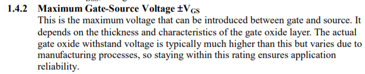
According to the documentation V_{gsm} is only valid in the on-state, so I hope that doesn’t include turning-on… Also, I find it really confusing that a MOSFET is rated for 100V, but can only handle a voltage differential of 30V.
The second switch is turned on first, it pre-charges the circuit at ~1A. Like Paul suggested. When the voltage is up to ~27.5V I engage the MOSFET, and turn off the second switch again.
I don’t understand what you mean.
Ah, also not shown, but I added a 100A fuse to the battery, and used the anti-spark XT-90 plugs there. Thanks for pointing that out.
Aaargh that’s an easy way to blow up the MOSFET. Remember that they are also blown up by dV/dt at the gate as well as Vgs. But also, any noise transients from your ODrives could potentially blow up your mosfet, I think.
And yes, Vgs is rated the same way as you rate a capacitor’s voltage (the gate is a thin film metal oxide capacitor) so it does include any transient between gate and source, including turning on.
This is why I stopped trying to drive power MOSFETs with anything except MOSFET driver ICs.
If you put a second resistor (actually needs to be lower, more like 6Ohm) between the gate and the boost converter, then you limit dV/dt and protect the MOSFET, but also you let the FET serve as the inrush limiter for the rest of your circuit.
But that point is moot, because I think you will destroy the FET with over-voltage at the gate.
This is a limitation of power MOSFETs.
N-channel MOSFETs should be used either on the low-side only, or with a gate driver, for these reasons.
Ah, yeah I understand. That actually seems like quite a big risk. I didn’t know \frac{dV}{dt} at the gate was such an issue. See, that’s why I like this route, I’m blowing up stuff, and learning along the way.
After your comment I read up here. Since I don’t need to switch very fast, and I have larger resistors available, I will go with one of those.
Looks like I got that right then. So, I’ll need to use my pre-charge circuit religiously. Although, I’m only 5V over what the documentation specifies, and it says that higher voltage should not be a problem. So I hope I’m lucky if I screw up.
I wonder if it might be a good idea to have a base voltage of 7.5V. That way my ODrives remain on at all times, but are in ERROR_DC_BUS_UNDER_VOLTAGE when I don’t need them. The added side effect being that my V_{gsm} is never exceeded.
Having said that, I think I have Source and Drain hooked up the wrong way round? If that is the case, then V_{gsm} makes more sense and is not as much of a problem… [edit: not the case, too bad…]
Sadly not…
When they invented and standardised MOSFETs, they tried (and pretty much failed) to communicate the idea that electrons are negative and they flow from what was (naiively/stupidly) called the negative terminal, to the positive one. They realised that traditional transistors collected electrons at the emitter and emitted electrons at the collector. The whole idea of electric current is backwards (ie the engineers and physicists had a huge fight in the 1980s and the physicists “won”, except they didn’t)
tl;dr: The the source is the negative terminal, and the drain is the positive terminal.
I need to look at that second resistor more carefully. I forgot the resistor to ground… You meant 60 ohm instead of 6 ohm right? Still thats 0.5 amps, what kind of switching time would that result in?
No I meant 6 Ohm. 10 would have done fine.
What I was worried about, is the gate being driven to halfway between 27.5V and 35V by means of a potential divider, had you gone with my initial suggestion of an identical 600R resistor to the positive supply.
But it’s all moot. Use an inert gas filled relay to mechanically open your circuit. It’s the only way to be sure.
I put the two resistors in parallel, that way the potential at the gate stays at 35V.
When my test setup is pre-charged, S is at 25V, D is at 27.5V, G is at 25V. Then when I engage the second switch G goes up to 35 V, and I can disable the precharging circuit. It appears to work, but I haven’t run a full load test yet.


 but I abandoned that approach and used proper gate drive ICs for all my mosfets after that.