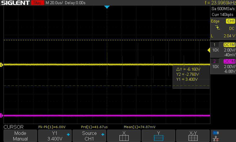
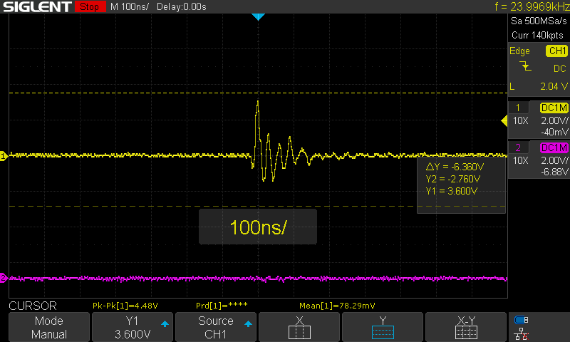
When trying to perform an index search with <axis>.requested_state = AXIS_STATE_ENCODER_INDEX_SEARCH in fw 0.5.2, the odrive begins the index search but immediately finishes due to switching noise affecting the index pin. It looks like the spikes are causing the odrive to ‘detect’ an index pulse and finish early.
I have 22nF caps between the encoder pins and GND, which should be filtering out a lot of the noise. It works correctly when I downgrade to fw 0.5.1. I get the following output:
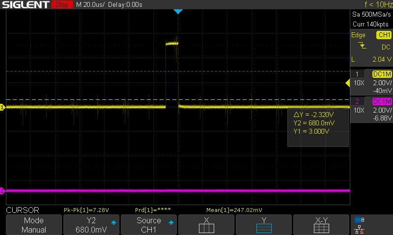
There is still some switching noise as you can see, but the index search works as expected.
Everything is the same electrically between the first two oscilloscope screenshots and the last one, so something must have changed in the latest firmware to cause the higher switching noise during the index search.
EDIT: I should also note that the index search has worked properly before on 0.5.2 so I’m not sure as to what’s going on exactly.
Do you mean around the encoder wires? To my understanding a ferrite ring acts as a low pass filter, and I don’t want to filter out the pwm signals on the motor wires that the odrive is producing. In any case, my main concern is the firmware upgrade showing a difference in noise levels on the encoder pins during calibration.
No I mean the motor wires.
You’re correct that the ferrite can act as a kind of low-pass filter, but they are only effective in the MHz-GHz RF range, not the 40KHz switching frequency. But even if they did work at low frequencies, the way they are placed in the circuit is what matters. (differential mode vs common mode)
Passing all three motor phase wires through the ferrite in the same direction means that it doesn’t act as a filter for the motor current because the three phases are supposed to sum to zero current at all times anyway (there should be no net movement of electrons in or out of the motor). Instead, it acts as a common-mode choke i.e. it restricts any net movement of electrons in or out of the motor, making it less effective as an RF antenna for the MHz-GHz components of the square switching edges.
Thank you for the information. Looks like it’s a good idea to use ferrites on my motor wires. Still curious as to why the firmware update made a difference, but this should help with noise in any case.
You’re saying it didn’t do this with 0.5.1? It could be there’s a difference in how the pins are configured, or a difference in the slew rates of the driver.
Yes I tested it on the same day with firmware 0.5.2, then immediately after downgrading the firmware to 0.5.1, and the difference can be seen between the first and last images I uploaded. The high frequency spikes (hard to see because of image compression) are consistently higher in amplitude in the first diagram, which is on fw 0.5.2.
@towen, I have a couple of further questions about the common-mode current. It seems like due to the common-mode current, the motor wires can act like an antenna and transmit RF noise. However, where is it originating from, and how is it being induced in the motor wires? Since all the motor phases are connected to each other, wouldn’t it violate KCL if you get a net current going into / out of the motor?
I just had a similar problem: The z-index would trigger randomly. I solved it by soldering a 1kOhm resistor on the z-index. This completely solved the problem for me. I’m not sure why, but it is something to try for people with similar issues.