Hi,
I am a Master student of Mech. Engineering, currently working on my master thesis.
A brief introduction to put my questions in context:
I will be using the ODrive (as of now I have the 56V, 3.6 version and two 5056 PM brushless motors) for the TORQUE control of a wheeled self balancing robot (similar to the Ascento, to make myself clearer). I stress " torque "control because I will be using some advanced MPC techniques and the natural inputs to the system are the wheel torques; therefore I need to control the torque as precisely as it is possible. I will then probably integrate the system using ROS and I plan of using a Raspberry Pi 4 B as the onboard computer (probably, I am still at an early stage).
My questions are directly meant to be answered by the creators of ODrive but please, feel free to contribute if you think you can.
During my degree (actually pretty recently) I studied some control strategies for PM machines (also for IM) and, in particular, FOC. My questions are directly related to the understanding of the current torque loop control implementation on the ODrive.
This is a not negligibly lenghty list of my questions:
To my understanding (please correct me if I am wrong), a regulation strategy in the so-called Synchronous Reference Frame is employed (in particular the qd0 frame). I know for a fact that the expression of the torque in the reference frame is 3/2P_pairs[PM_flux*i_q+(L_d-L_q)i_qi_d]. I read in the forum various instances suggesting an estimation of the torque using only the i_q component and the Kv rating of the motor. Isn’t that “wrong” in the case we are not dealing with an isotropic machine? In that case L_q and L_d would be different and the torque would depend also on the i_d component.
Given a torque reference, how does the torque loop compute the currents i_q and i_d? Is it through the MTPA technique (“maximum torque per ampere”)? I would guess yes, since trying the torque control on the motors I see a set i_d different from zero.
Since i_q and i_d are measured, how can I use them to compute the “exact” value of the torque? Or equivalently, how do I get an estimate of the PM_flux? Is it something which I can extrapolate from the motor datasheet (e.g. through the Kv)?
I also read that the current loop (and also position and velocity loops) runs at 8 KHz. However, could someone provide me an estimation of the maximum theoretical BW of the current loop, supposing I am using ATM102 encoders with 2048 PPR settings (4x2048 with quadrature)? I know that, as a rule of thumb, the BWs of the loops are generally chosen 10 smaller proceeding towards the outer loops, so that the inner loops can be seen as instantaneous by the outer loop. And I also know that, using asymmetric PWM and sampling at the right instant of time during the duty cycle, the theoretical BW of the torque loop cannot be higher than approximately the Carrier frequency /20 (if I remember correctly). Does the ODrive implement asymmetric PWM or simply a symmetrical one?
Are the current gains automatically chosen depending on the measured physical parameters of the motor (self inductance and resistance)? In the control scheme I studied they were chosen in order to perform a zero-pole cancellation with the motor plant, so that the current transfer function could be approximated with a first order one. Is that also the case of the ODrive?
Is an antiwindup scheme implemented?
Are there any feedforward therms after the two i_q and i_d regulators compensating for the back-emfs?
Given my configuration (56V ODrive, 5056 motor, ATM102 encoder, 4000mAh 6s LiPo battery), which is range of torques I can expect to be able to command? Also, with what resolution? Knowing these specs is crucial for two reasons: first, I need to know how good a torque control I can achieve and, secondly, I’d like to be able to include the actuator (meaning the ODrive) real characteristics in my future Gazebo model of the robot.
I hope I didn’t make too many questions for a single discussion.
The following is an image of the control strategy I am referring to. I’d like some feedback on the differences between this and the one the ODrive implements. I hope it will be pretty much self-explanatory (P/R indicates a polar to rectangular transformation and R/P vice versa) .
Yes, it’s wrong. We assume an isotropic motor with equal Ld and Lq. It’s not a perfect assumption but it’s generally close enough for the 5065.
I will have to check with Oskar.
Your torque is ~proportional to Iq_measured via the motor.config.torque_constant
About 2kHz 2000 rad/s at the torque controller (current_control_bandwidth setting)
Yes, we measure R and L and set the current control gains according to these parameters and current_control_bandwidth to achieve critical damping.
Yes, mostly. There is clamping with desaturation. Not every saturation case is accounted for - for example you should avoid saturating your voltage control by running your motor too fast, because the torque controller doesn’t account for it (I think?).
The ODrive has ~ 0.5A noise for current shunts, and the current controller PWM timings are something like 4500 clocks so Vbus * 1/4500? I’m not exactly sure about the resolution but I imagine it’s swamped by the current shunt measurement noise.
Re control strategy:
Looks pretty similar to what we have in devel - only small difference is that we only measure 2 shunts and use KCL to derive the 3rd. Speed observer exists but doesn’t currently use torque to estimate the speed (no motor inertia estimate)
First of all, thanks for your fast response.
So you assume an isotropic machine. However it is not so clear to me why, since you assume L_q=L_d, during my past test I was reading an I_d different from zero (in the sense that it is not negligible compared to the shunt noise you were referring to). These days I will conduct a simple static test with a precision weight scale and a 3d printed arm to measure the torque I can output from the 5056, the resolution of the commanded torque and how the commanded torque is close to the real one. It might well be, since I am new to ODrive, that during my previous tests I was hitting one of the limits; this time I will set a reasonably high current limit and vel limit and I’ll see what happens.
Please let me know on point 2, when you have time; I would assume, since L_q=L_d, that the current loop simply makes use of the torque constant of the motor. If that is the case, comparing the “real” expression with the one suggested in the Docs, the following relationship should hold: 3/2P_pairsPM_flux=8.27/Kv. Does someone know the reason of such a relationship between the “real” torque constant (assuming an isotropic machine) and the one proposed one in the documentation (on the left of the =)?
If you assume L_q=L_d as you are saying, this would mean that the i_d setpoint would always have to be to 0, since this component does not generate any useful torque and only contributes to the Joule losses in the winding. Is that correct?
Also, since the ODrive measures the quadrature and direct axis inductance (L_q and L_d) to achieve critical damping, why not use them to compute the full expression of the torque? That way the assumption of isotropic machine would not be needed anymore. The only problem I see is that, to compute the optimal i_q and i_d (which now is different from zero) one would need to employ something like the MTPA algorithm for choosing the right current amplitude and phase in the qd0 frame.
When you say that the scheme is something similar to what is in devel, does it mean I can use it if I flash the right devel firmware on the ODrive? Or is it still not a stable/completed firmware version?
It appears to me that the devel version of the firmware implements some more advanced control features; how can I flash the devel firmware to my board (I have an ST-link)? I am quite new to this and I am finding the Githib page a little disorienting. I would really appreciate some directions on how to use the GIthub page to flash/modify the firmware. Any reference to a guide is also much appreciated
We only measure the inductance in one location, and then assume L_q = L_d = measurement.
We have a firmware developers guide on in the docs! It explains everything regarding how to get started with modifying, flashing firmware etc ODrive Firmware Developer Guide | ODrive
Regarding point 2 from earlier:
Paul: Does ODrive use MTPA?
Oskar: Not really. I mean yes in the sense that if Ld = Lq, then Id = 0 is MTPA, but yeah nothing that is optimal for a non-isotropic motor.
You should join us on the Discord, there are quite a few motor designers and robotics people who hang out there.
Thank you very much for clearing up my doubts. I will join the Discord server for sure.
I did the tests on the torque control resolution and the preliminary results seem quite good: I am able obtain at least 0.01 Nm resolution. I didn’t push my trials at higher resolutions, since my measuring apparatus is not so reliable.
However, I am obtaining a possibly strange behaviour from the 5056 motor in torque control mode.
I measured the static torque produced by the motor by holding the rigid arm which is attached to the shaft still against a flat surface.
When entering the closed loop control (after having set the torque control mode) and throughout the whole test there is an audible noise from the motor.
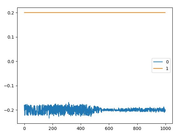
This reflects quite evidently in a noisy behaviour of the measured torque, which is clearly visible in the Liveplotter; however, if I turn the shaft slightly one direction the noise is greatly reduced (both audible and in the measured torque). There’s this strange anysotropic noise.
You can see this phenomenon in the following picture, where the moment the noise goes down is clearly visible:
Does someone have an idea why it happens and if it is solvable? I would expect something like that if the FOC wasn’t working properly and the PM_flux axis wasn’t properly synchronized with the rotating field; however I don’t think this is the case, since the encoder has a much higher resolution compared with the degree step I have to impose to the shaft in order to cancel the noise.
I see. But it is strange that the amplitude of this noise depends on the rotor position. If this was due only to encoder/meas. noise I would expect the amplitude of the noise to be more or less constant wrt rotor position. Are you sure that this is not a symptom of something else? Did someone encounter this behaviour previously?
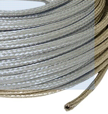
Consider that I have shielded the encoder cables with this (I have wired the cables myself since at the time of my purchase the encoder cable was not available):
I stress that the noise is not only in the measured signal but manifests itself also with an audible noise (similar to the noise the motor makes when using position control with non-tuned loop gains).
I would exclude encoder noise due to improper wiring, since during position control I don’t get a noisy signal, rather a well conditioned one.
Yes, the audible noise comes from the current shunt measurement noise. This is well established. You can set motor.config.requested_current_range to a smaller value if you want to reduce it.
The encoder noise could exacerbate it but i don’t expect it’s a bit contributor
Perfect, thanks again. During the test I left the current limit to 10 A, which was never exceeded. So I think reducing the current range will not be of any help, but I’ll try it anyway. By measuring the torque with an external device (external weight scale with a resolution of 0.1 g and a 3d printed arm with 10 cm distance between shaft and contact point) it seems however that this high frequency noise is somehow filtered by the dynamics of the motor, which pretty much exerts the correct value of the torque. Might also be due to a filtering of the weight scale, but I’d exclude it since that configuration of the scale gives me a theoretical measuring sensitivity of approximately 10^-4 Nm.
I read somewhere in the forum that shunt resistors are replaceable. Should I need less noise, is it something advisable and, more importantly, achievable via a simple soldering iron? Do I need a better equipment? How do I select the new resistors?
In future versions of the board, have you considered using different hardware for measuring the current to increase the performance of the current sensing (for example hall effect transducers)?
Thank you for the very well formulated questions. I’ll start by answering your initial set.
Yes indeed we use the dq0 frame (we assume no connection to the star-point, so we neglect the “0”, and just call it the dq frame). Yes the torque equation you mentioned coincides with the theory I reference, some of it reproduced here. Yes ODrive does not have any MTPA, and simply assumes an isotropic motor, and set the i_d setpoint to 0 and map torque linearly to i_q. We may add MTPA in the future for motors that have some saliency (reluctance torque). Or you can add it and submit a pull request!
We use a simple motor.config.torque_constant to scale torque setpoint to a i_q current. This config value is supplied by the user. You can calibrate it experimentally, but you can also get it from 8.27 / (motor KV), of course there is some tolerance in the KV rating. I think the i_d setpoint should be 0, but i_d measured may be some small value due to noise/tracking error.
The torque constant as per above gives the relation between current and torque (3/2 and pole pairs already factored in). To get pm_flux_linkage as per the theory, you would instead do 5.51328895422 / (<pole pairs> * <Motor KV (rpm/v)>).
Yes the system is built with the assumption is that the inner loops can be taken as instant. I am actually not familiar with the terminology of asymmetric vs symmetric PWM. We use standard Space Vector Modulation and center-aligned PWM to generate it. The automatic tuning of the current controller assumes that the bandwidth is significantly lower than sample period, such that we can take a continuous time approximation of the system. If you instead take the correct discrete time system, or tune it manually, I actually don’t see why you can’t tune it all the way up to the same speed as the sample rate, i.e. a “one shot” controller that tries to apply the voltage to take away the current error in a single cycle. I wouldn’t recommend it though as the current sensor noise is a bit too much for that to be stable I would guess.
Yes, and yes exactly it is a motor pole cancellation tuning, and indeed it should yield a first order closed loop subsystem that has the bandwidth as specified. (I think @Wetmelon mentions critical damping, but actually I think he is referring to how we tune the 2nd order speed/pos observer. The current controller pole cancellation tune is 1st order, so there is no under/over/critical damping to speak of)
Yes, both the velocity control integrator and current control integrator has anti-windup. Focusing on the current controller (since you will not use velocity control): It is very similar to your block diagram: saturate in polar coordinates, i.e. clip velocity radially towards the origin preserving the voltage angle. (I think this may not be optimal, but it was simple to implement to start with. We may make something more sophisticated later.) We don’t have it like the diagram with antiwindup gain towards the error sum, but rather use a fixed decay rate to decay the integral voltage towards 0 if the final voltage was saturated.
Yes there is some experimental stuff like @Wetmelon mentioned. However as it is right now it’s only useful if the speed estimator bandwidth is higher than the current controller bandwidth: because we don’t have torque based prediction in the estimator (yet, we want to do this). If they are similar bandwidth or the speed estimator is slower, then the speed feed-forward isn’t helping.
It’s mostly based on the current sensor noise. It is about 0.25A rms at 8kHz sample rate at the default gains (you can change the gains and get lower sensing range but better noise). This means that the achievable motor current depends on the bandwidth of the current controller. I guess it can be summarized as 3mA/sqrt(Hz) noise density. As for modelling the ODrive accurately, I would suggest that you dig right into the FOC code and lift out the relevant core control laws and reprodce them in Gazebo. This is why open source is great.
I think the audible noise is pretty much entirely due to the current sensing noise, and probably almost nothing from the encoder. You can try setting motor.config.requested_current_range = 25 and then save config and reboot. This sets the current sense amplifiers to a higher gain which gives a higher voltage signal to measure, which reduces the noise somewhat.
Better current sensing performance is one of many key improvements of our next generation hardware.
Thanks Oskar for you very punctual replies. I think your answers and Paul’s ones clarified the vast majority of my doubts/curiosities.
There’s only one thing I can think of which is left. How is the estimation of the L_q (or L_d, since you assume isotropic machines) carried out practically during the motor calibration?
For measuring L (= Ld = Lq), we simply emit a squarewave voltage along the alpha axis in the stationary frame, and look at the current response also along alpha. The rotor angle is not considered, so we don’t know along what rotor frame axis (angle in dq) we measured.

 It explains everything regarding how to get started with modifying, flashing firmware etc