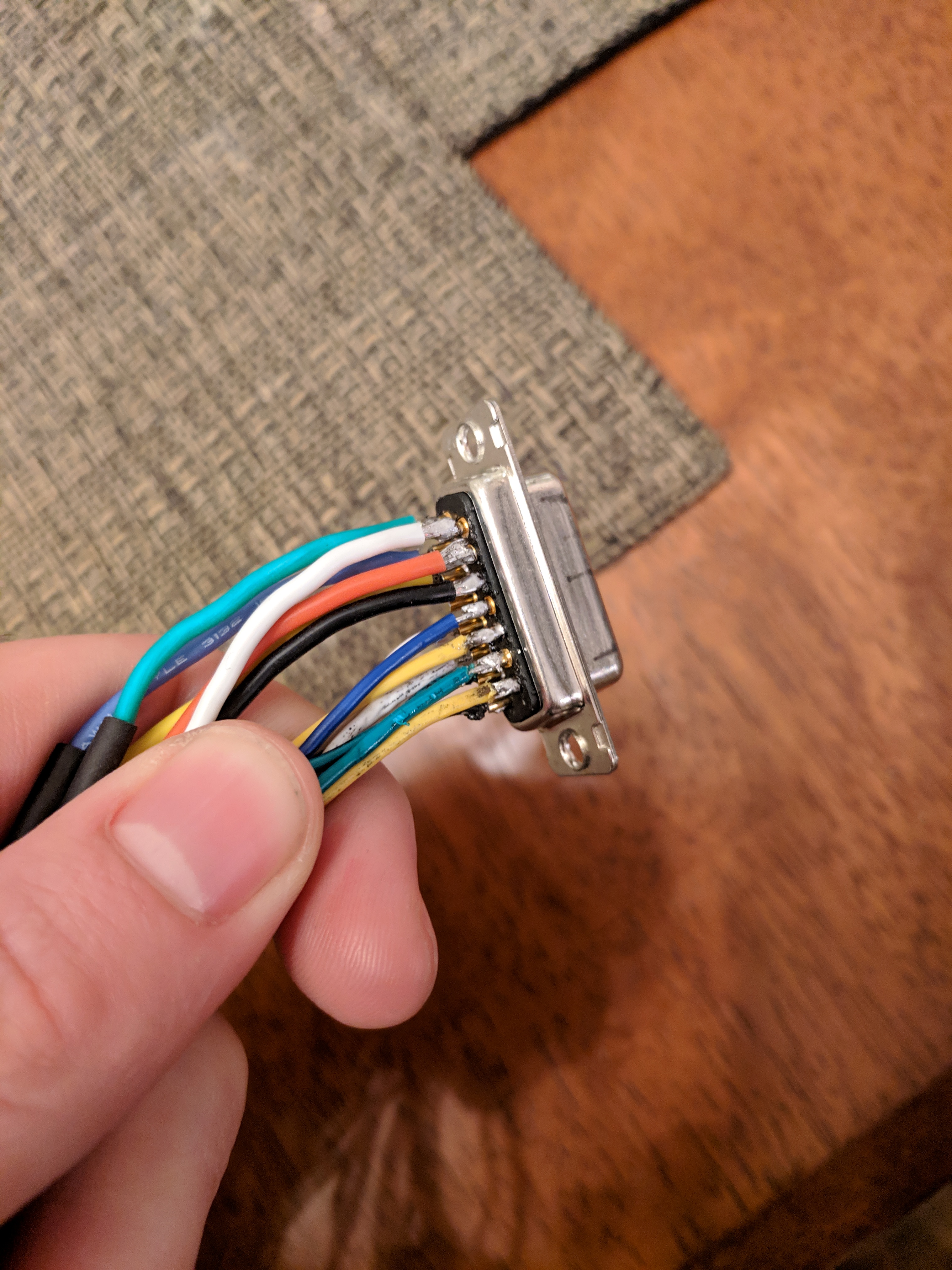
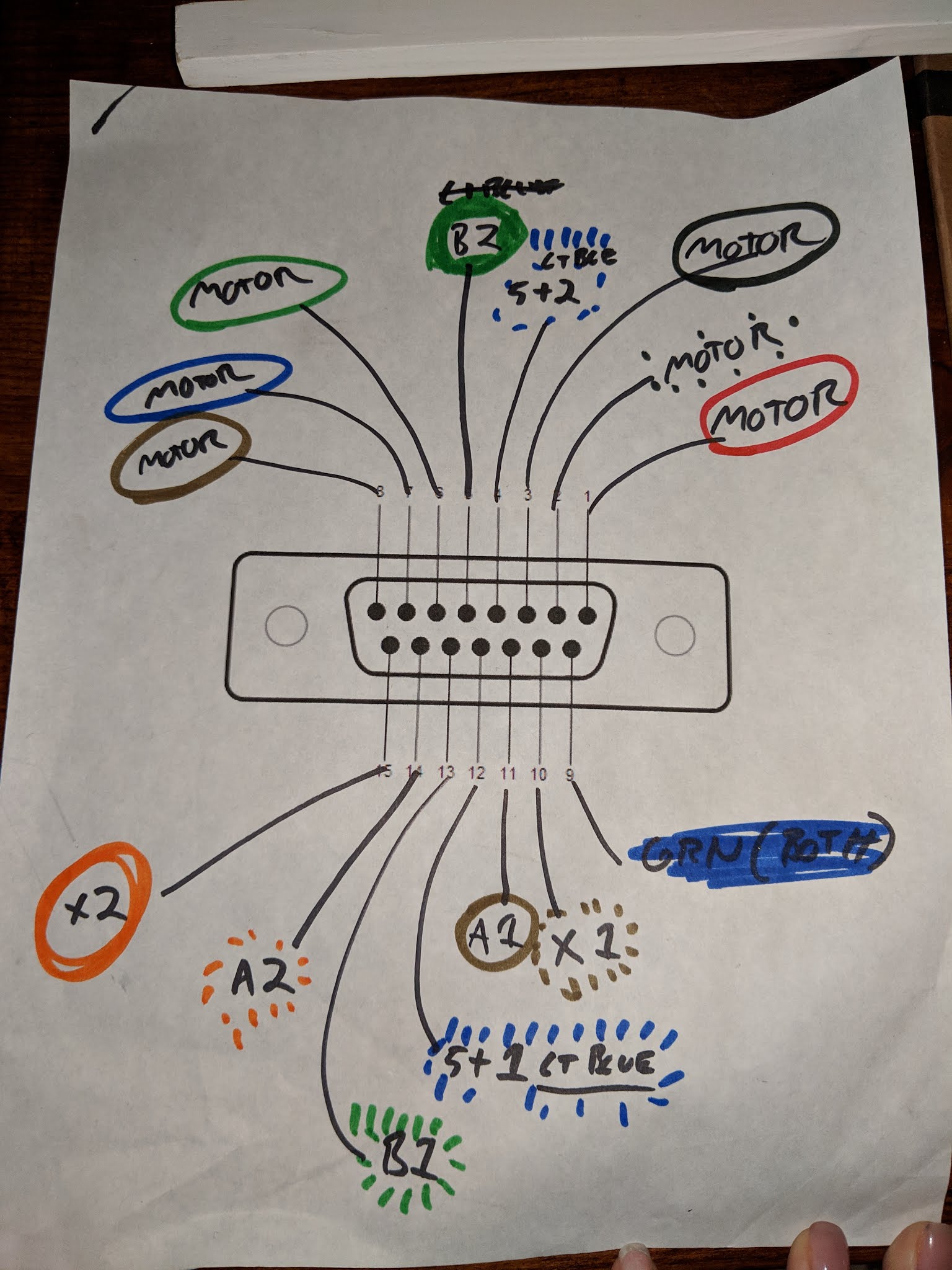
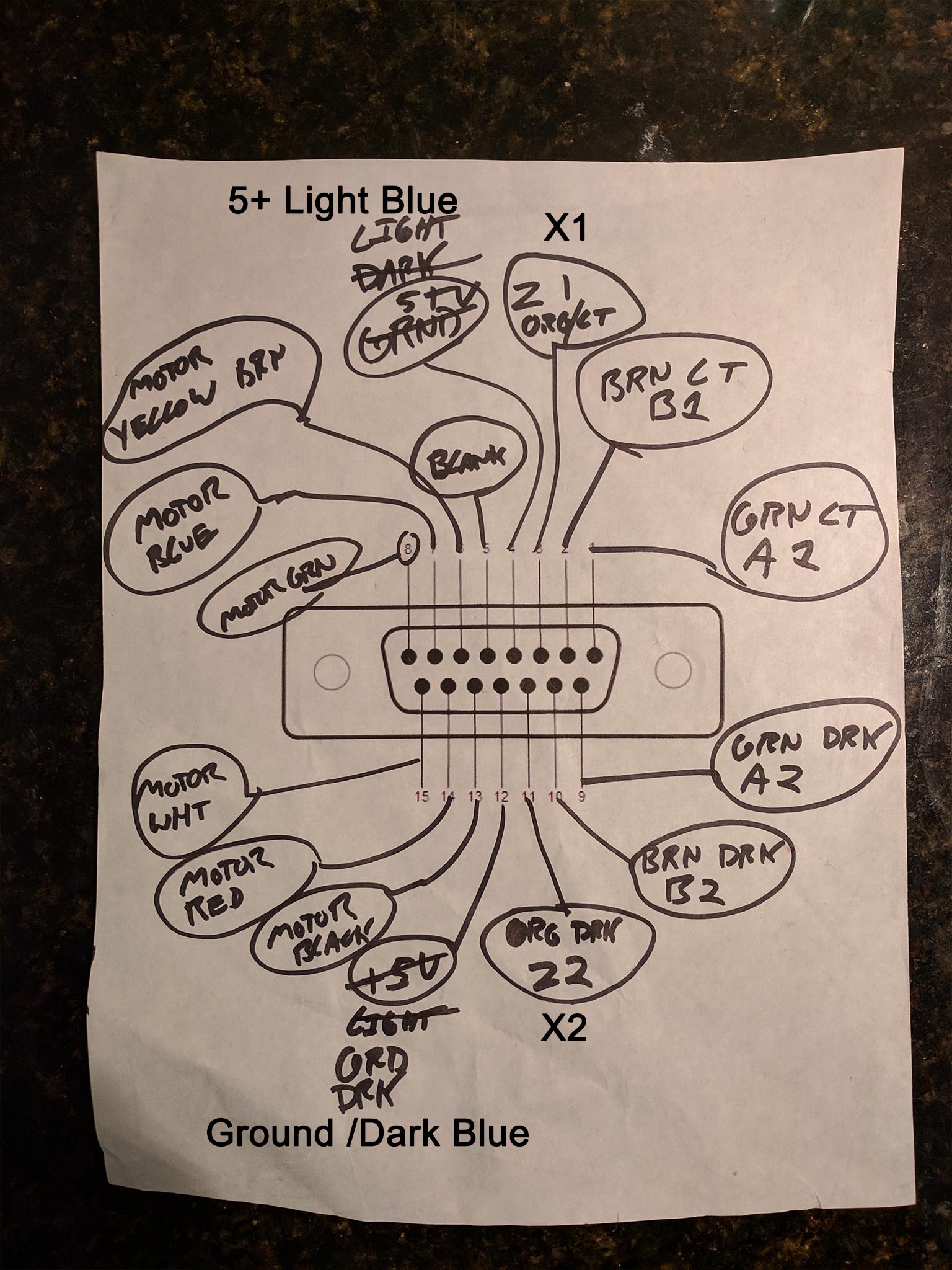
I have been trying to build a cable / connect setup that works for two motors and encoders in one cable / connector. I have been trying to use a DB-15 connect using 6x 18awg motor wires and 8x CAT 7 encoder wires with the encoders sharing power and group and with the shielding attached to ground on the ODrive side. Also the motors have a max 10amp rating which is why I am using 18AWG.
It seemed like it would work after several tests with the DB-15 connects, but now that I have everythnig built it is not looking so great. The motors don’t want to index correctly sometimes, calibrate correctly other times. Sometimes during calibration it done one full turn one direction and another full turn that same direction, and it does this randomly. The worste part is, one day it mostly works fine, the next nothing works right. I have checked all my connections under a microscope and nothing it touching.
When I check erros it generally gives “0x2” so I am guessing there is interference between the motor power and encoders cuasing it to srew up… input? Ideas? Thanks!
Did you check with an oscilloscope the noise in the encoder wires? Maybe they are picking up too much noise if running in parallel to the motor wires.
If that is the case, i would think about using a differential transmitter/receiver for the encoder signals, so that the common mode noise is cancelled out almost at the end of the line (just before reaching the odrive)
Also, I think I figured out part of my problem, @Jorge I used an oscilloscope trying to look for interference, although I don’t really know what I am looking for. What I did see was the fact that during calibration the length of the encoder signal seemed to change. The mechanical mechanism that the motor turns was the problem. During calibration, there would be a variable amount of resistant which I am guessing screwed up the calibration most of the time but not every time. So I increased the calibration current and worked on the mechanism a bit and it seems to work most of the time… I still have some questions about saving calibration but I’ll start that on a different thread.