Hey Fellas 
Just ordered my first ODrive. I’m currently in the process of building a small lathe. It’s NOT a CNC-lathe, it will be mostly manually controlled using electronic handwheels and some Arduino / Teensy 3.5 logic / magic.
The main spindle motor is a brushless servo that comes from a steering-assist assembly from a car, 24V, 600W, 5300rpm, pretty high torque. It’s all belt-driven and I’m using a 1200ppr encoder from Omron for spindle indexing, threading and for the ODrive. At first I wanted to control the spindle using a chinese brushless controller, this thing is unsatisfactory though. To save me some time and potentially a lot of work I went with an ODrive instead.
Have a look:
imgur gallery
What I absolutely need from the ODrive, with the help from an Arduino:
- velocity control via PWM (via Arduino)
- direction change (via Arduino)
- some PID-thingy to maintain a constant speed at various loads
- a somewhat definable speed-up/down of the spindle
- needs to able to be turned “off”, meaning that the spindle must be able to rotate freely
Am I able to achieve all this with the ODrive and an Arduino? From what I’ve learned so far this should be an easy task?
Any suggestions, any pitfalls to avoid?
Thanks a lot! 
3 Likes
That’s an impressive little lathe you have there. Everything in your list should be easily doable with odrive provided your power supply is up to the job at hand. Remember that if your motor is rated at 600W it may be able to draw as much as 3 to 5 times that at peak output. Without knowing more about your motor its hard to say just what kind of power supply you will need. The good news is that many people (myself included) have been able to pickup cheap mult-kW server PSU’s off ebay that are more than capable for the task.
Another suggestion would be to consider using UART instead of PWM to communicate between your Arduino and your odrive as this will give you access to many more options via your control panel. For example, you can have a toggle switch being monitored by your Arduino which when opened has the arduino send a command to your odrive over UART to move from AXIS_STATE_CLOSED_LOOP_CONTROL to AXIS_STATE_IDLE and thereby disabling your motor but keeping the odrive active and ready to go at the flick of a switch. If you were using PWM only then you would need to remove power from the odrive to disable the motor. If you decide to do automatic threading down the road then you could also set this up to work in position control mode.
An example library is already available for here.
Also, as Odrive is still in active development there is always a small chance that something may go wrong causing your motor to go out of control. For this reason I highly recommend you include an e-stop in your setup that either removes power from the whole system (not always easy if its setup for high currents) or pull the reset pin on your odrive low, which will disable it.
Wow, thank you very much, this has been very helpful!
Power supply is a generic 1.2kW SMPS made of the finest Chinesium available to mankind. Should be enough - I hope.
Your advice with going for UART instead of PWM is exactly the reason why I made this post. Thanks a lot! 
An emergency-stop is of course included, for safety reasons alone. I’ve grown pretty attached to my fingers over the years 
Seems like I have to look into UART. I’m pretty new to electronics and Arduinos especially. Love to learn though.
Most likely I’ll be spending quite some time here as soon as my ODrive turns up at my doorstep.
Thank again!
Cool project! I’m in the process of converting my 12x36 lathe over to CNC. Working lately on the spindle motor and control. Same requirements as you, with an additional “dividing head” mode.
What’s your plan for the tailstock? Namely “locking” it when using a live center or similar? Just gonna apply some constant torque, or do you have any sort of physical brake or similar? It looks like the tailstock has a spider on the back end - is it going to double as a steady rest?
Well done so far. Very modern!
edit: also, hop on Discord; that’s where the action’s at.
Nice to see that there are more machinists around here
I’ve added two screenshots from my CAD to the imgur-gallery (see first post).
Basically, the tailstock will be locked using two electromagnets. They are “hidden” in the base of the tailstock slide and clamp the tailstock in position via a steel rail that is located between the two linear slides on the machine bed.
Each of those holds 400N, I expect this number to be a little lower due to the restricted width of the steel rail. Using two electromagnets should be sufficient though.
I really don’t plan machining steel on this machine, so I don’t have to worry about the magnets accumulating chips. This would be a major issue when machining steel.
I’m just lazy and this is the simplest and easiest method of locking the tailstock that I’ve come up with. Baiscally, I just need to flick a switch to lock my tailstock. Couldn’t be any more conveniant than this 
1 Like
Where did you bought the spindle bearing block, it looks like this is a off the shelf part?
I might have a different name.
Also looking into building my own lath somewhere in the future.
Anyway great project!!
Go to Aliexpress, search for “4th axis”.
There’s various versions and sets, I bought the one with the ER32-collet and the tailstock with the live centre.
I needed to change the bearings and the spindle itself is also self-made, regarding the headstock I really only used the aluminium part itself.
It’s a pretty cheap and easy solution if one needs a headstock and / or tailstock. Needs some work though, the bearings inside the headstock are not suited for being used as a lathe.
Here’s some more information on the motor I intend to use:
Another imgur-gallery
The magnets in the rotor are arranged in three axial rows, 6 magnets per row, each row a little shifted. Is this a problem?
So… This means that this is a 9 slot 6 pole motor? Or is my logic wrong? Makes this sense? I’m sorry if this is a terribly dumb thing to ask…
From the photos it looks like your rotor has skewed magnets which will aid in reducing cogging torque at the expense of a slight reduction in peak torque. So overall a good thing.
1 Like
Yeah, cogging is a no-issue with this motor. Runs very smooth even at super-low RPMs.
Are my thoughts on poles/slots correct?
Its a little tricky to count them in the photo but that sounds about right from what I can see. One way to test is just to hook up your odrive when it arrives, input the settings and check that it behaves as expected. Any strange behaviour (not rotating smoothly, different levels of holding torque at different positions etc) then you know your numbers are not quite right. No harm will come if you input the wrong numbers when trying.
1 Like
Ok, thanks a bunch!
Will try it as soons as the ODrive arrives. The main spindle is done, finished the last part yesterday in the evening. I can hook it up right away.
It hasn’t been shipped yet and it may take a while to get it over the pond…
Well. Lots of other things to do in the meantime.
2 Likes
How did this work out, and what car was that steering assist motor from?
Works fine. Currently building the rest of the controller board.
I honestly don’t know what car brand this motor was used for. Those are sold on Aliexpress in vast quantities.
The motor is awesome, so much torque - especially with an ODrive…
Feel free to ask!
Very interesting, any more details on your project anywhere? Videos perhaps?
Thanks!
As of now there isn’t anything interesting to say. Finished the layout and did all the soldering for the spindle controller, now I need to do the programming.
I also made some progress with the milling of the carriage, think I can finish this tomorrow.
Will upload some new pictures when it’s finished.
1 Like
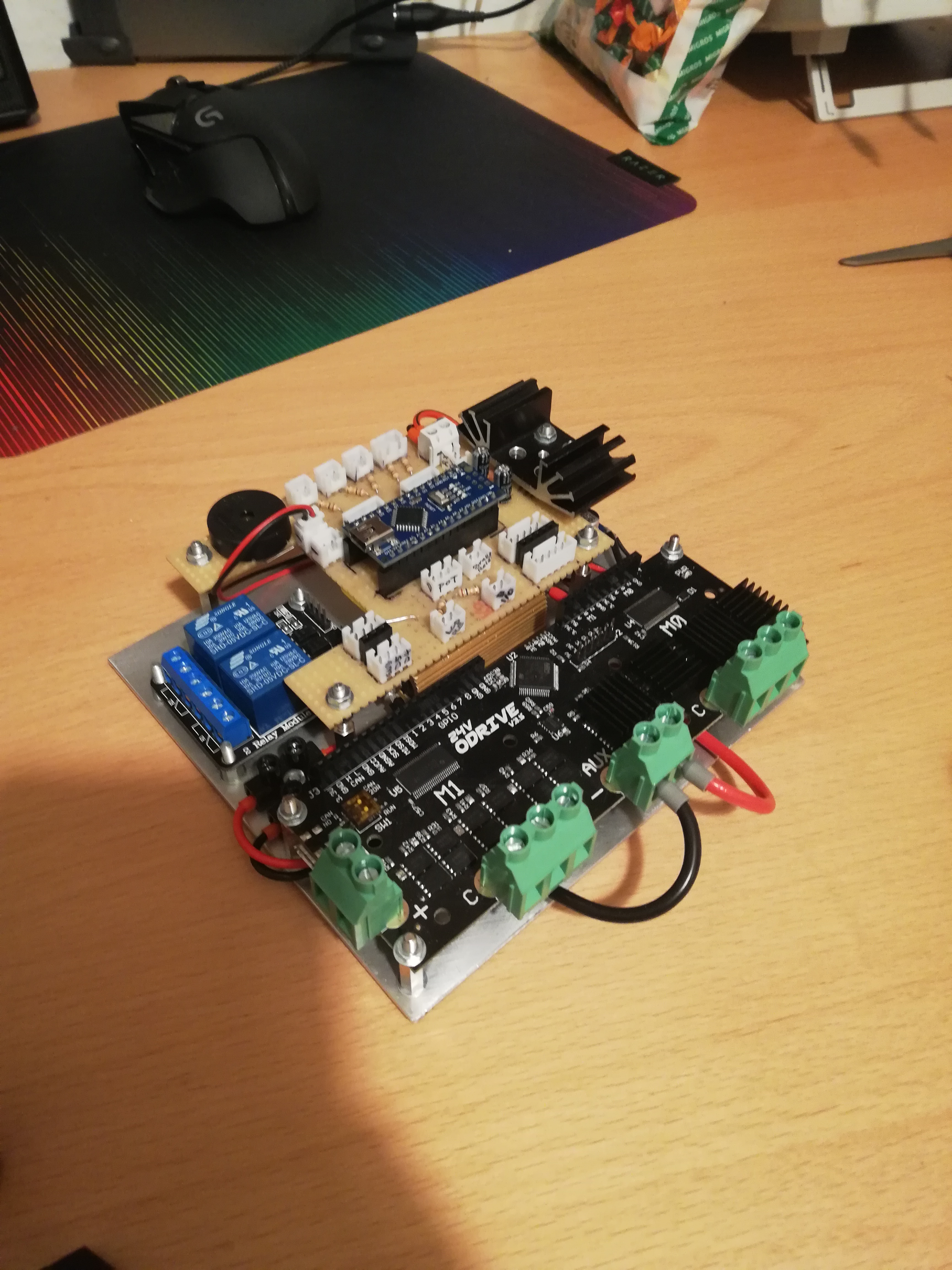
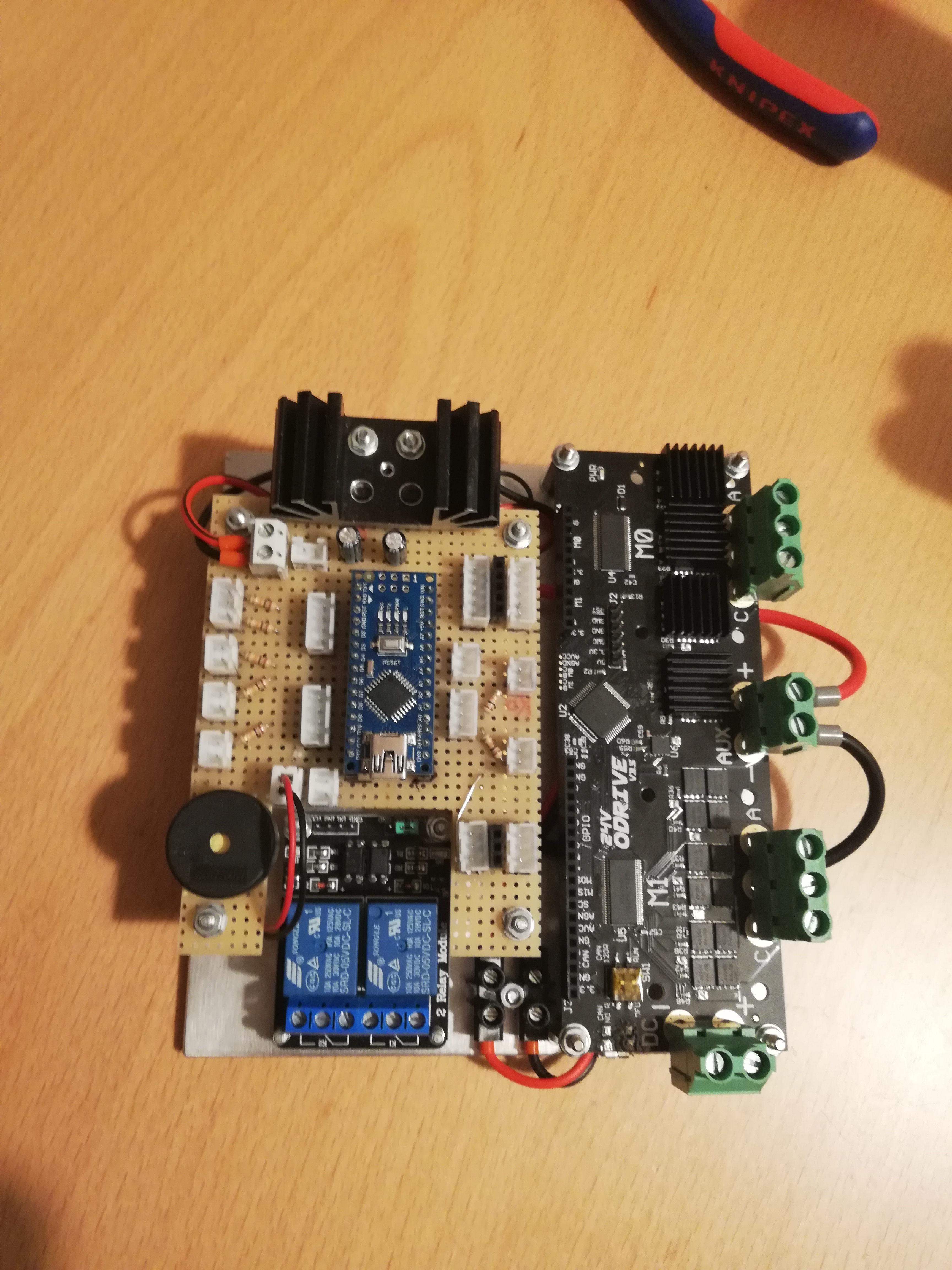
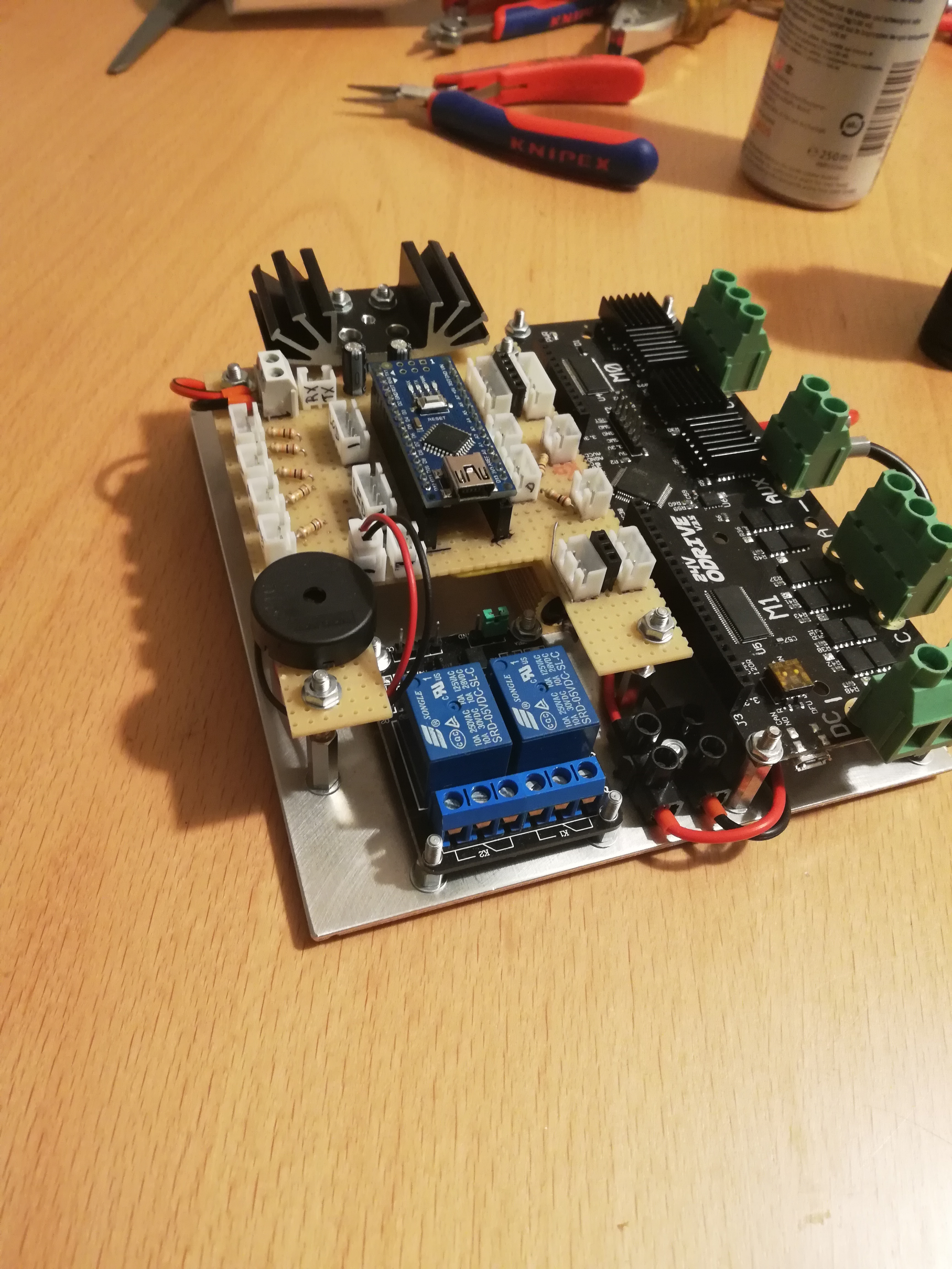
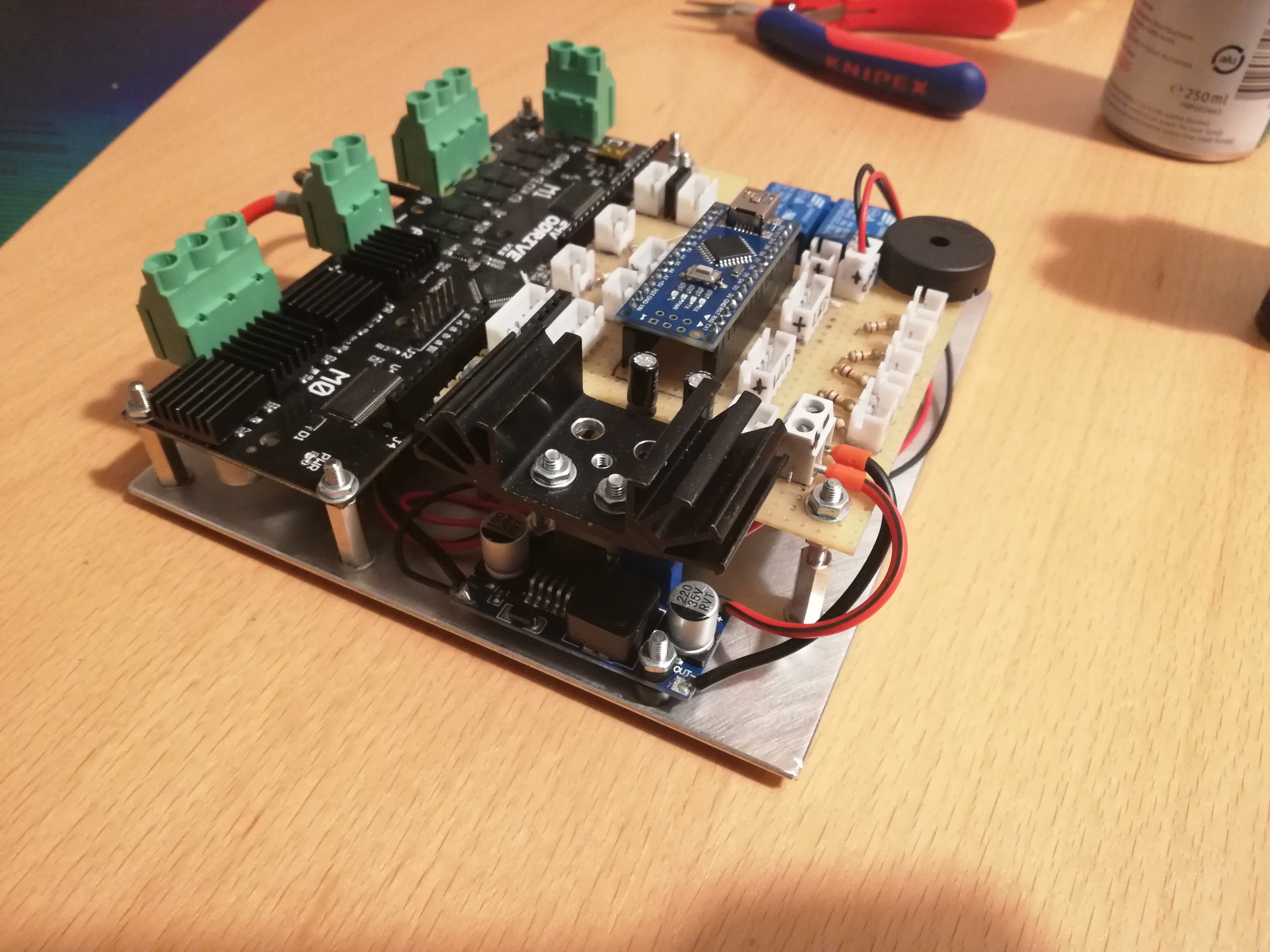
Finally made the controller… There’s an Arduino Nano, a relais-board (for the electromagnetical spindle brake), a small buck converter and lots of connectors for all the buttons, switches, displays and whatnot.
Need to start the coding now…
This was a lot of work, especially all the soldering of the connectors.
Wanted to have the ODrive and all the other components relevant for the spindle controller on a single board of Aluminium, that’s why I went that route…
4 Likes