Hi Guys,
First off, great job for everyone working on the ODrive firmware. It’s written really clearly so that even I can understand most of it; certainly way better than what Microchip or TI has in their examples.
I’ve been studying the BLDCs and FOC for a couple of days now and I get how the math works. I have however encountered a problem with the direction of currents through the windings of the motor. The way the ODrive firmware is written, it seems the direction of currents is the opposite of what I have imagined them to be. The SVM function (utils.cpp) is the one which bothers me.
Let’s call the SVM function with a simple vector alpha = 0.2 and beta = 0.0. The vector is clearly in sector 1, true. The function gets this right. But then the function calculates the PWM duty cycles and returns this:
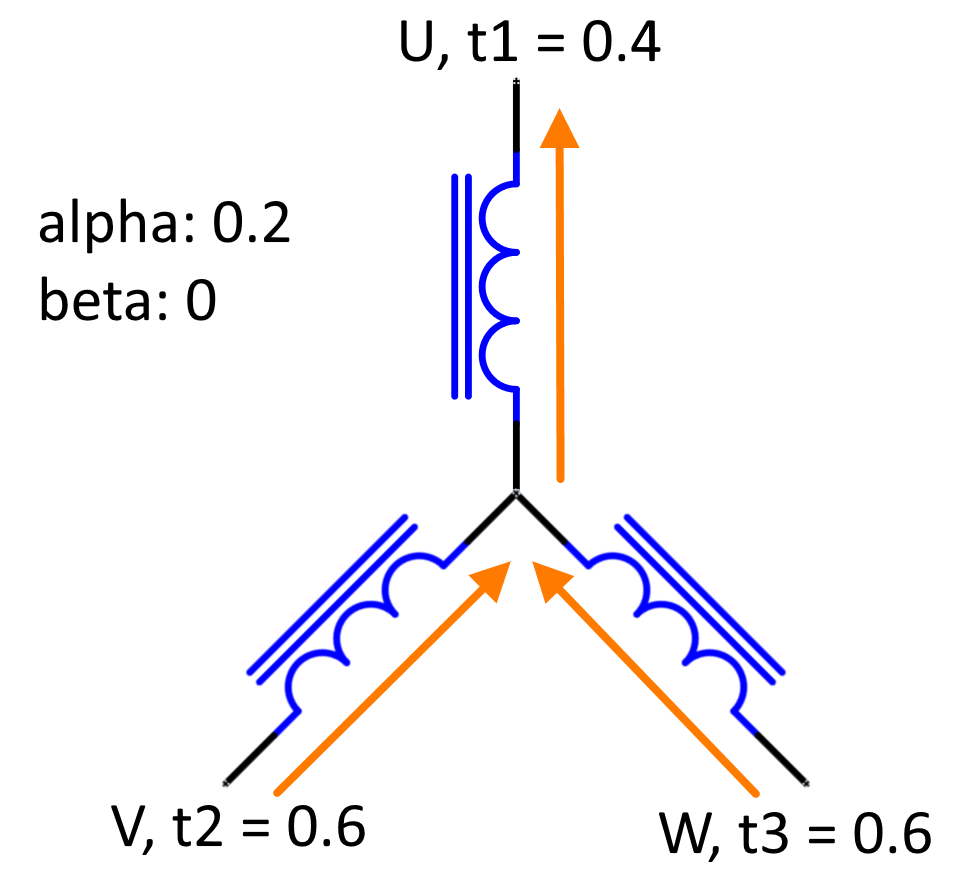
t1 = 0.4, t2 = 0.6, t3 = 0.6
With these values, the voltage at U will be lower than at V and W and thus, the current will be flowing “from” the winding center point, through the U winding and into the half bridge. Thus the current will have a negative sign. Shouldn’t it be the other way around? I always imagined that this is true:
- The current is positive, if it is flowing from the half bridge into the winding to which it is connected
- If alpha is positive and beta is zero (so theta = 0°), then this means positive current through the U winding and negative current through V and W (each one half)
I’ve drawn a simple image to demonstrate this. So to ask plainly, what am I getting wrong?
Thanks for any pointers,
Ivo