Hey y’all!
Been setting up two odrives to fight one another for the purpose of characterization (e.g. efficiency: electrical power in vs. mechanical power out). To do this I have one motor (motor1) with an odrive pro in velocity control, and another motor (motor2) with an odrive pro in torque/current control. With this setup I can set motor1 & motor2 at different constant torque & constant velocity setpoints. Motor1 will dictate the velocity, and motor1 will try to apply the target torque at that velocity (Motor1 is quite a bit larger, so motor2 can’t easily overwhelm it). I have a two 3S1P battery packs powering 1 odrive each, and I have oscilloscope readings of battery voltage & current for motor2.
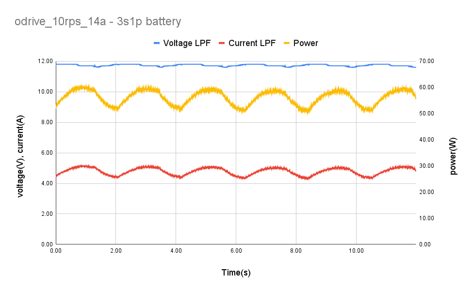
When running this setup at various constant current & speed setpoints I am seeing some low-frequency ripple in the battery current & voltage (around 0.5Hz). Attached is a plot of an example at 10rad/s and 14A q_axis. I low-pass filtered the battery voltage & current data w/ a 10Hz cutoff
Interesting, not entirely sure. What does the ODrive report, with vbus_voltage and ibus? It would be interesting to see some traces in the GUI. You may want to set ibus_report_filter_k to about 0.075, corresponding to a 100Hz LPF.
Could you also post the raw data dump? And maybe a picture of how you’re scoping everything?
If this was proportional to motor speed, then I’d expect it’s eccentricity in the magnetic encoder.
Is that plot from the drive motor or the load motor? Do you think it could be an issue with the velocity gain tuning?
The vbus and ibus from the Odrive were reporting very stable readings.
I think we’ve isolated the issue which does seem to be an issue with the oscilloscope settings.
It appears that this is a result of aliasing, basically we had some significant high frequency noise, but were sampling well below nyquist. For now the problem is resolved. Thanks for the help!