The 80% I think is a guard against the drive energising any of the coils with DC, which could cause a fire in the event of a software bug.
Also, the ODrive is intended primarily as a servo drive, not a powertrain drive. In servo systems it would be an extremely rare event (basically, a fault) to ever get to 100% bus voltage at the motor, because you need control headroom for a servo. If you get near 100% in normal operation then your voltage is too low, basically.
If for some reason the hardware timers of the chip are set to more than 80% PWM demand on any phase, then ERROR_MODULATION_MAGNITUDE is set.
On that topic, I’m brainstorming what would be involved to convert the motor dyno to a chassis dyno. This allows us to do a full systems test of the car running a full simulated competition run (40 mins).
In this mode, I would need to have a motor acting as a generator off the back wheel. I can give it a correct torque vs speed profile (generated from MATLAB).
However, now the load motor & ODrive will need to sink something like 500W (I’m not sure if this would be continuous for the full 40 mins, depends on steady state aero losses etc).
The question is, what do I need to do ODrive wise to handle this?
I’m confident the ODrive can run in this mode, but clearly I need to do something with all the energy I’m sinking.
Could I put 4 lead acid batteries (cheap from scrap yard) on the bus side that would be charged up during a run?
What do I do with the energy after a run, can I feed it back to the grid for example?
Or can I use a 2 way power supply & no batteries to go straight to the grid.
Yep. That should work fine.
Provided the batteries are happy to be charged at 500W without exploding, that is.
Also, you’d probably want to put your bench power supply (if you need it anymore!) at the float voltage of the batteries (i.e. 48V) otherwise you’d always be charging them.
That’s called a 2- (or 4-)quadrant power supply. They are expensive.
Initial reading says you can charge a lead acid battery at ~25% of its rated capacity.
E.g. to take a 500W load at 10.5A (500/48=10.42A), I’d likely only need 4x42Ah 12v cells.
I’m not sure for how to discharge them quickly after a run (to prepare for the next). I suppose I could purchase a cheap grid tie inverter & have that drain the cells to a set voltage perhaps.
The newest software (rc0.5.0) includes the ability to regen back to the power source up to a configured value, and if you’re generating more current than the configured value it will start dumping to the brake resistor. Also, the brake resistor / bus voltage suppression was improved, and it’s much better at clamping the bus voltage.
What specific to that motor gives it poor static torque performance?
I.e what should I look out for on a motor to avoid this issue?
Something like this might do: https://www.aliexpress.com/item/32364452023.html
Only trouble with that is it has some residual friction / cogging so you won’t be able to set it to a zero or a completely constant torque.
Not sure what you mean by “static torque performance” but I’ll take it to mean “low torque-ripple” since that was what I was going on about.
Most PM synchronous / brushless motors designed for power density (i.e. all hobby motors) have cogging which is an effect of mixing permanent magnet rotors with iron stators - the magnets ‘prefer’ certain positions around the motor, where their total ‘closeness’ to the iron has local maxima. This is also known as a varying ‘reluctance’ iirc.
Cogging can be compensated out in software using a high-resolution encoder. Measure the current required to hold position with no load at every position on the motor’s rotation, and then add that as an offset from a lookup table in future. The ODrive has some (Beta) support for this.
The second issue is ‘magnetic hysteresis drag’ - this is also a product of using permanent magnets and iron, because as the magnets move past the iron, they will polarise it this way and that. Re-polarising a piece of iron has a finite energy cost, so you effectively feel friction on the motor even if there is none in the bearings.
so-called coreless, ironless or slotless motors do not experience any cogging or hysteresis drag, but they are more expensive and have a lower torque density (since they don’t use iron to amplify the field of the coils)
And thirdly, you have torque ripple caused by the geometry of the motor. The torque produced by the coils for a given current will change slightly as a function of angle. For example if the magnets are flat, then this will cause some variation (some motors e.g. expensive T-Motor use curved magnets to reduce this effect) or if there is some variation in the air-gap between the magnets and the coils.
The cheap 8318 produces a lot of torque because it has big magnets and many poles - but that also increases the hysteresis drag, cogging, and other torque-ripple effects.
You could look into ironless axial-flux motors. They can even be wound by hand, much more easily than other types of motor.
I know I will run out of RPM on the test motor before the sink motor (so all is fine here), but how would i go about checking that the sink motor can handle the torque range I want to measure?
Based on an 8318 motor with max power of 2900W, at 14S (58.8V peak), I get a max torque of only 4.1Nm. I will probably not need to run much pas the 2.1Nm rated torque of the test motor, but it’d be nice to have the capability to run in this higher power region.
100 rpm/V equates to about 0.1 Nm/A iirc, so you’d need about 43A to produce 4.1Nm. From my experience with 8318 Kv100 motors, they can handle up to about 30A at stall, i.e. 3 Nm. They could probably sustain 43A, but only when attached to a propeller and nothing else (ie a great big cooling fan)
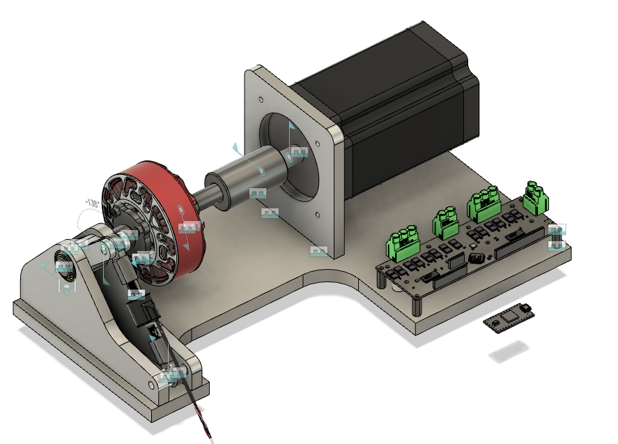
Where’s your encoder in that CAD?
Also, what kind of coupling is that? A solid coupling might produce some strange results, as it will be straining your bearings against any mounting misalignment / runout.
Spiral couplings are terrible for stiffness, and they fail easily. I’d suggest double disc couplings, but they can be quite expensive.
You need an encoder for each motor. You cannot use the encoder on the test motor for commutation of the load motor, because there is a compliant mechanism in between. If the coupling were to twist by one degree, it would have a significant impact on the relationship between current and torque in the load motor.
Also, you don’t want to have to recalibrate the load motor every time you move the set screws on the coupling.
Also, ODrive does not support using two motors with one encoder.
Unless it was an incremental encoder I suppose, in which case you could connect the same encoder to both inputs. But it’d be a nasty hack.
Maybe you could run the load motor in sensorless mode… It depends if you are interested in low speeds (below 600rpm or so) or not.
Sensorless mode works well when there is no load at low speeds (i.e. with a propeller), but it cannot produce a reliable torque at low speeds, and is useless at stall.
You can get off-axis magnetic encoders which use a large ring-magnet with many poles. They are extremely precise, but unlike on-axis magnetic encoders, they are not absolute, so they will require calibration on every boot-up.
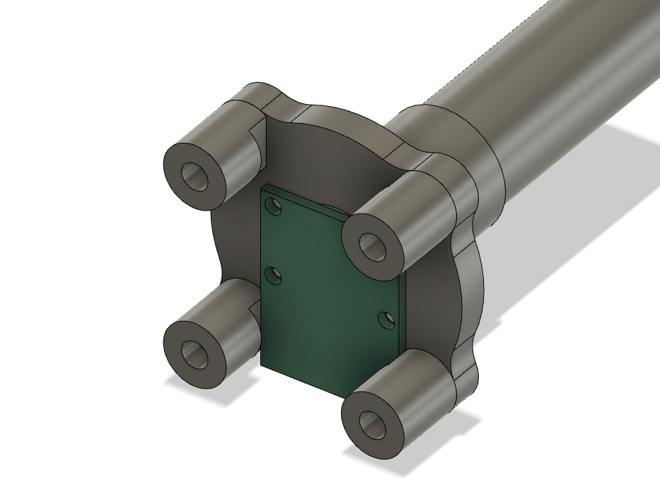
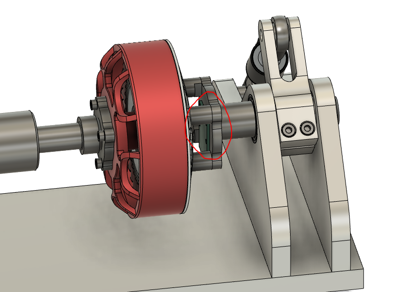
Annoyingy the 8318 bolt pattern isn’t wide enough for them to clear without going down to really thin wall thickness spacers. I may wrap the edges of the PCB with some electrical tape to prevent a short.
I suppose for attaching the magnet to the motor shaft, I could print a very small adapter or perhaps just get away with glueing the magnet to the end of the bolt and then spacing the sensor PCB accordingly
Yeah, fast-setting superglue works really well in my experience.
The spacing to the magnet can be as little as 2mm. You could probably make those mounting legs shorter (& therefore stronger). Perhaps have some triangular buttresses to support them when the whole thing is going to be under torsion?
You could add four 2.5mm pillars to locate the holes in the PCB, instead of screw holes. Then use tape as you say to secure it.
How is your adapter made? Is it 3D printed or are you sending off for some parts to be machined out of stainless?
You could always make your own PCB for the AS5047p I suppose.
Ah cool yeah I’m planning on spacing up the encoder once everythings assembled. I’d rather give myself too much space to work with rather than too little in case I need to modify parts.
Yeah the bulk of the frane/flanges will either be steel or ali machined in Uni.
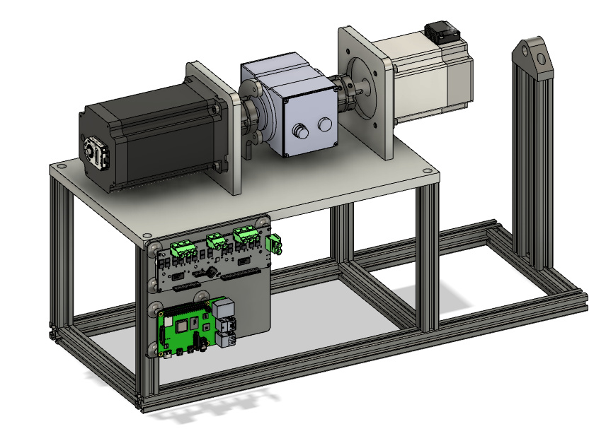
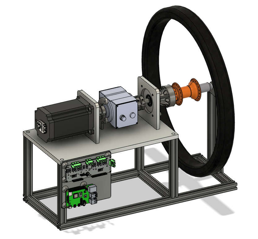
Thought I’d update this post given most of the mechanical design work is now done and components are starting to be ordered over the Winter exam period.
It was looking like the 8318 was going to be somewhat limited in terms of peak torque compared to the motor we wanted to test.
So, bit of a rethink and I’ve updated things to reuse our previous BLDC motor (uses built in Hall effects) with a very fancy rotary torque sensor that the team is kindly being supplied.
Shown below are CAD images of both powertrain test mode, as well as the wheel inertia measurement setup.