Motor Modeling etc

I was looking through the motor guide and thought it could use some expanded modeling (at a glance, we seem to be neglecting rotor inertia, bearing dynamics, and gravity). Creating a spreadsheet like this could be used to simulate a trajectory or later to follow a trajectory much more closely through the use of feedforward control, and is considered necessary to reasonably control serial robotic manipulators (i.e. motors and links one after another) well.

Is there interest in more accurate dynamic modeling? Or, to avoid endless spreadsheets, a control method that could learn its own parameters (i.e. adaptive control) and report them back? My formal background is in high performance robot control, so this is an area in which I might be able to contribute.

3 Likes

In my use-case of a motor lifting a weight linearly, the model parameters are gravity and inertia. It would be great when we implement closed loop servo control if these parameters could be autodetected. With my current commercial servo controller, I have a hard time manually adjusting its PID parameters so they are satisfying over a large speed range.

I don’t think they belong in the motor guide though since these parameters vary depending on the setup.

I don’t think they belong in the motor guide though since these parameters vary depending on the setup.

I agree that they might not belong in the motor guide, but they still affect how to select a motor. And rotor inertia isn’t setup specific, it’s motor-specific, unless you machine something different, I suppose. The truth is that this won’t affect motor selection very much, but it does significantly affect motor dynamics. So more credence to your suggestion that something like this might not belong in the motor guide.

Is vanilla PID the control method currently being used? Sorry for my ignorance, but I haven’t dived into the code much yet. PID works well on regulators, when you’re trying to reach a static position, but not so well tracking a trajectory. I’ve seen dynamic accuracy improved by 20-30x over PID by using more advanced methods.

Is anyone aware of plans to implement more trajectory-aware or disturbance-rejecting control methods like sliding mode, feedforward, or inverse dynamics? I’d love to help with implementing these if we have the need. High performance! These methods would be particularly strong with systems that have high disturbances, like cutting force disturbances from a CNC machine.

2 Likes

Yes, but everything moving you connect to the motor will add to the inertia. Maybe the rest is negligible in some applications, but for a electric bike for example there’s a lot of momentum stored in the wheel.

No, I was talking about another servo controller. Logosol ls-231 to be specific.

Maybe the rest is negligible in some applications, but for a electric bike for example there’s a lot of momentum stored in the wheel.

When I say rotor inertia I just mean the rotor shaft, not all the attached parts that effectively make the full rotor. There are cases that rotor inertia will significantly affect dynamics, like when a motor is geared significantly the rotor inertia is effectively multiplied as well, but I think most people are using direct drive. I don’t think it will affect motor selection much, but the point is that it rotor inertia is easily modeled and compensating for it will make motor accuracy better.

The real point I’m trying to make is that performance will improve if we leverage a more complete motor model in something like inverse dynamics control. We can get ok performance until then, but without leveraging what we know about our system (rotor inertia, load, gravity), performance will never really by “high” performance, it’ll just be “fast” performance. Notice how wavy the lines are in the High speed servo motor demo from a couple years ago. More can be done here if we really want high performance. I’m really just curious if people are working on this, or if it should be something I implement on my own.

Yes there is a plan to do model parameter estimation and hence add feed-forward control. Let me share with you the vision I have for this, which I open to comments and suggestions.

We have a plan for an off-board, offline auto-tuning workflow that will use excitation pulses and captured data sent up over USB to a computer during commissioning. We plan to use SciPy and Jupyter to implement a workflow consisting of model parameter identification, followed by offline simulation-based parameter optimization: similar to Simulink Design Optimization Toolbox.

Specifically, this is how I envision the roadmap of features to reach there:

  • Live plotting of states, measurements and control effort in Python host.
  • A oscilloscope-like buffer in firmware that can trigger on an event and hence log at the full sample rate of the control loop into a buffer: then transfer the buffer to the host.
  • Make a continous-time model of the system with SciPy’s ode-int.
    • Example: The model takes the initial position of the mass (load), some specified parameters (mass, friction coefficient, etc), and then uses the logged motor current as input to simulate the system by ode integration. This generates various outputs, including position over time.
  • Using SciPy’s optimization features, we let vary the model parameters and use difference of the logged position over time with the simulated one as the goal to minimize. This should let us identify the model parameters.
  • We should come up with some set of excitation/stimulus signals that the firmware can do to generate currents and movements that will help reveal model parameters.
  • We can now use the estimated model parameters to add feed-forward terms to the embedded controller.
  • We need a trajectory generator and/or a feasability filter (rate limiter, etc) in front of the controller such that we can feed it feasible setpoints and hence have feasable feed-forward control effort.

We can then also tune the feedback gains offline, in simulation, once we have accurately estimated parameters and validated the model. This can be done with various objective functions that we automatically optimize, or we can let the user drag sliders around and get instant simulated response to tune against.

3 Likes

I like this offline auto-tuning approach a lot. It limits our ability in the future to adapt motor parameters on the fly (e.g. if a robot picks up a heavy box), but would be amazing and probably more accurate than adaptive control for any application that doesn’t have dynamics that change permanently and significantly during operation.

We should come up with some set of excitation/stimulus signals that the firmware can do to generate currents and movements that will help reveal model parameters.

If the algorithm ends up being similar to how adaptive control gets dynamic parameters, this will be as much art as science. We’d anticipate some dynamics proportional to acceleration (e.g. inertia/mass), some to velocity (e.g. damping/friction), and some to position (e.g. motor torque ripple). Others I can think of, like coriolis forces, aren’t present with just a single motor.

Great to know that you think this approach is appropriate.
Yes I think there are many extensions we can do in the future, including expanding the model to include coupled axes (series joints, CoreXY, etc).The nice thing is that the framework should be able to handle this, all you have to do is extend the model.

One easy way to handle picking up objects is to force the user to supply the mass of the object, and model only the added mass. Of course this can’t handle picking up an object with random mass. But I think we cover a large portion of use-cases with the original approach.
In the future we can add some online adaptive thing, but that is something I’m happy to leave for later.

Meanwhile, one thing that is possible to do with the proposed workflow is to do a form of robust control: we can let the user supply a range of load masses that are expected, and hence we can force the tuning in simulation to be stable over a sample of all possible load masses. This will of course reduce the performance, but we can use it to help people tune something that can be robust to this, if that is required for their application.

So here is my half-baked ideas for stimulus: Just some super basic pulse current stimulus at close to the motor’s current rating (to get strong acceleration/mass visibility) that iteratively gets longer and longer in duration until we have also reached some threshold speed/displacement. Once that has identified the basic response, we can tune the basic feedback gains, and hence do closed-loop stimilus. For these, a set of a few different frequency and amplitude sinusoids could be appropriate. Maybe throw in some steps? Yes definitely some art with the science ;D

1 Like

We use model based control in STMBL.
The user enters resistance, inductance, system inertia, max motor current and number of pole pairs. At runtime each PID loop is scaled and clamped by an electrical and mechanical model of the motor.
This allows motor independent PID gains.
Measuring resistance, inductance and system inertia in the drive is on the TODO list.

Using SciPy’s optimization features, we let vary the model parameters and use difference of the logged position over time with the simulated one as the goal to minimize. This should let us identify the model parameters.

So, what model would we try to fit to? If you don’t have one in mind, might I suggest:

Torque = inertial_load*acceleration + damping*velocity + gravity[theta] + torque_ripple[theta] + disturbance

We’d obviously tell users to leave the motor undisturbed during this test so we can neglect the last term. If we get enough data points, we could fit a torque_ripple function of the form these guys have used. This should make motor performance reallly nice and smooth, even at very low speeds.

inertial_load would be a constant, damping would be a function of the form a + sgn[theta]*b, and the gravity would have to changed based on loading conditions but should be something like a*sin[theta].

Meanwhile, one thing that is possible to do with the proposed workflow is to do a form of robust control: we can let the user supply a range of load masses that are expected, and hence we can force the tuning in simulation to be stable over a sample of all possible load masses

I’m sure this idea would work, but sliding mode control is also a form of robust control, and usually improves performance. I know augmenting the control scheme on hardware is more difficult than what we’re proposing here, but it might not be that much of a performance hit.

So here is my half-baked ideas for stimulus…

Sounds great!

For these, a set of a few different frequency and amplitude sinusoids could be appropriate. Maybe throw in some steps?

I like this approach because smooth sinusoid-y motion and step commands are common, so we’d be “training” the motor on practical moves, which I think is the right approach.

I’d love to help design the Python implementation side, but I’ve never contributed to a Github project before. Are you looking for contributors? If so, is it straightforward to become one?
1 Like

Yes contribution is very welcome. At the most basic level, contributing is as straightforward as submitting a pull request from your fork of the repository: Instructions.
In this case the content of the road-map involves a lot of features, so I think it would be beneficial to do some discussions before you get started to:

  • Identify where in the roadmap makes the most sense for you to get started
  • Decide the scope for the first feature you want to start on
  • Discuss implementation ideas
  • Share some knowledge about likely gotchas

I’ll reach out to you in a DM.

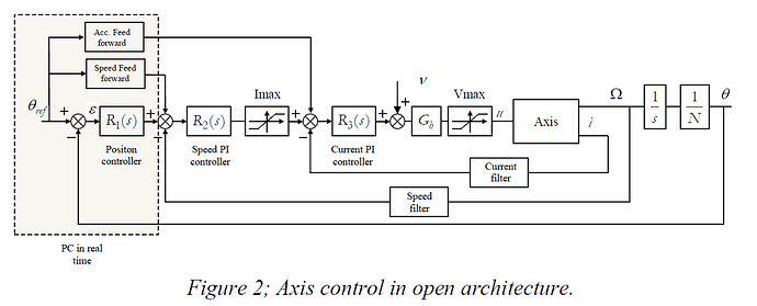
@William_Weatherholtz, to answer your question from before about the controller, the ODrive uses a cascading controller with Feedforward terms, similar to the following:

Pedro Rodriguez-Ayerbe, Didier Dumur, Sylvain Lavernhe. Axis control using model predictive
control: identication and friction effect reduction. 3rd International Conference on Virtual
Machining Process Technology, May 2014, Calgary, Canada. 8p., 2014.

I’ve also made a Simulink model if you have access to MATLAB/Simulink. The plant is envisioned as a mass on a belt drive actuator, and the default settings have the load travelling 4.9m in 1s, start
to stop. Positional accuracy is within .1% of desired (i.e. ~4.8965 when commanded to move to 4.9m at 4.9m/s) with hand-tuned gains. https://www.dropbox.com/s/0h3vaksolgvd3zm/ODriveModel.slx?dl=0

I’ve compiled a bunch of literature on various autotuning methods. One I’m trying to find again that I don’t think I saved used a relay-autotuning method first to get close to the global optima, then a frequency-based / sine wave tuning method for more accuracy. I’ll let you know if I find it again.

We’d obviously tell users to leave the motor undisturbed during this test so we can neglect the last term. If we get enough data points, we could fit a torque_ripple function of the form these guys have used. This should make motor performance really nice and smooth, even at very low speeds.

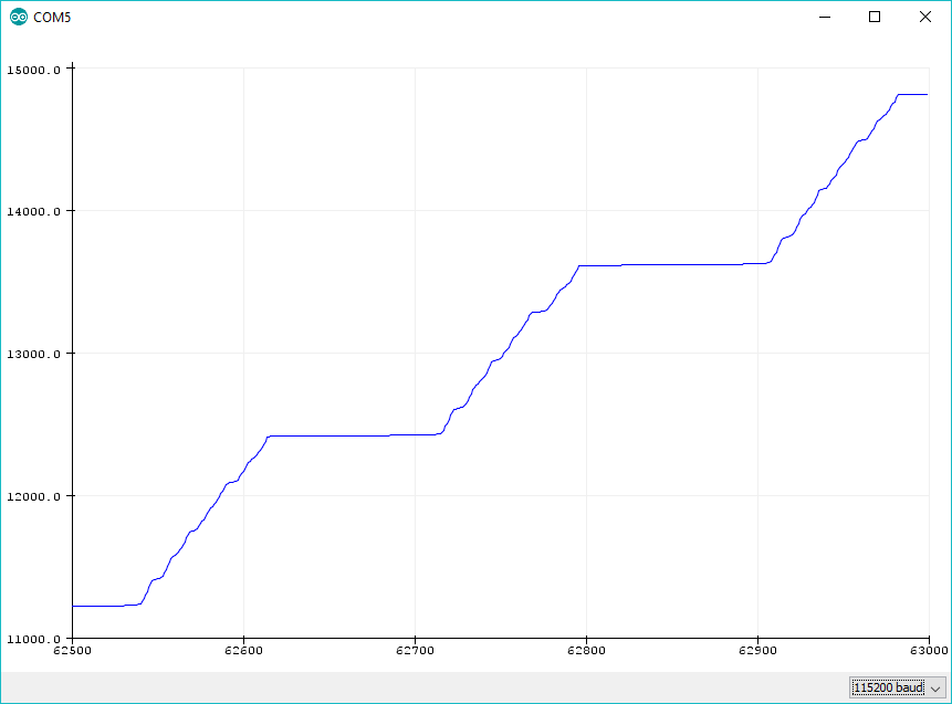
I saw that paper a while back, and we actually planned to integrate their research into the ODrive. See the Github Repo. Right now, ODrive definitely experiences some serious torque ripple!


Position vs Time graph - slow speed velocity control of N5065 motor.

Thank you for turning me on to that paper. It’s been an interesting read so far!

0.1% accuracy is pretty good! I’d be interested in RMS error over the whole trajectory, which you’ve given me the tools to look in to. I’ll post back here once I’ve gotten results.

I saw that paper a while back, and we actually planned to integrate their research into the ODrive

The model isn’t that complicated, iirc, so it should be something we could get reasonably good parameters on through taking a lot of measurements. My vision would be to have ODrive output a lot of data (using DMA or something to a USART buffer), then have a computer figure everything out, then feed results (like friction model coefficients) back to the ODrive. Seems achievable to me. Is there a different way this is planned to be implemented?

Sweet, now we don’t have to draw our own diagram, this is very close to perfect. It’s missing that the encoder velocity filter comes from position of the plant, not velocity. Also I don’t know what Gb is. And of course our position controller isn’t on a PC.

How were the feedback gains tuned here? I feel like while the N5065 is quite coggy, with stiff feedback gains I feel like it should be a bit better than what you show?

I think we are on the same page.

Just the default settings that ship w/ the firmware. It was also running very slowly. Something like 500 counts/second?

Ah okay, yeah the default feedback gains are super slow/sloppy to avoid problems if the user hooks up a low inertia high Nm/A motor.

Hello,
I would like to make a SCARA type robot with inverse dynamic model control. My idea is to calculate in each iteration the torque needed on each join in order to make a predefined move. I will regulate this torque with a P or PI controller to follow the path. All I need is to be able set a current (I have seen that it is possible) but also to access the position very quickly (to read the encoder).
Do you think it is possible with the ODrive ?

Cordially
Adrien

If you plan on writing this to be running on an RTOS thread directly on the ODrive, I’d say absolutely it should be possible. Running externally on the PC or similar, I don’t know if that’s a good idea.

Hi,
In humanoid robotic we begin to work in whole body torque control computing current from inverse dynamic and motor model.

I think doing inverse dynamic on the PC is mandatory if you use several DoFs, as some computation are involved.
You may want to extract position and velocity from Odrive, and send back desired current.
In my experience, 1Khz whole body control frequency is enough (at least for humanoids).

I suggest to use the UART com bus on Odrive with a real time interface to avoid possible USB latency.

By the way, in my lab we developed an opensource and efficient library to compute inverse dynamics of multi-body systems called pinocchio

Here you can see some preliminary result of torque control (not with ODrive but with old brushed DC motor)
The 12 DoF of the legs are torque controlled at about 700Hz.

I’d be really surprised if there weren’t much better ways to communicate than UART. But then again, it’s out of my wheelhouse.

Off the cuff, I’d opt for RS232/RS485 and communicate over ethernet. USB is not meant for long wires.