we are having a problem in our system while using the odrive trying to reach a specific angular location using a BLDC with 1:10 gear ratio - I will attach the full spec of the motor after giving the full details.
The system is a rotational one with maximum unbalance of 12.5[Nm].
the motor we are using is a 3 pole motor 24 VDC with a rated torque of 5.5 [Nm] ( After the gear)
a rated current of 13.6[A] the maximum torque is 16.5[Nm].
we trying to move 45 degrees with the our system and we are having oscillation while trying to reach the exact location which should be approx. 45º ± 1º.
my main question is that our motor might be not suitable for our application?
or it is got something to do with the gains of the driver?
Yes, this sounds like you might want to do some tuning. ODrive uses a cascade control - you can see details about the control loop structure here: Control | ODrive
I will try to expand my explanation even more to try to make it clear:
1.we are trying to jump 45 degrees with our system from one position to another.
2. the system have two different kinds of loads (Inertia) - one is extremely light compare to the second one.
3. when we are trying to jump with from one angular position to another with the second inertia (2 Kgm^2) - we are having oscillations around the angular position we are trying to reach.
4. in order to understand it better I tried to separate the mechanical system from the motor - and I connected an inertia directly to the motor shaft - and to enter a sin wave with different frequencies.
5. First when entering a high amplitude of to sine wave - the motor shaft and the inertia was jumping and did not gave any sine wave at the output - when I extremely minimized the amplitude to the input sine wave the motor showed a very good behavior and as a perfect sine wave at the output.
Finally my question is what could be the main reason for the those “jumps” with the higher amplitude?
could it be the that the commutation of the motor?? and if it is - how can I try tune it ? and how can I make sure that the commutation is done in a good manner?
we do have an encoder and we are using it for the positioning control feedback - as you can in the motor spec attached - we the motor phases , hall sensors and the table next to it referring to the encoder output.
we are suggesting that problem might be the motor commutation process , and we do not fully understand how to make sure that the commutation process of the driver is done , or to make sure that all calibration process ?
do you have any idea how to make the perform this process?
Thanks for the data. I don’t see any issues in here, the ODrive appears to be working perfectly. Can you show me in the data where there is a problem if you perceive one?
thank you very much for your quick respond! - yes, you are totally right the data sent to you was recorded with a low amplitude sine wave , so the system reaction was as expected - a sine wave.
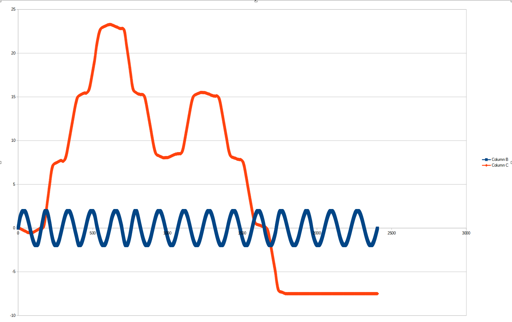
please see now attached to the link bellow the data set with the “bad” recordings , as the input amplitude was higher - please give us your thoughts what could be the main reason for that?
The blue column is the input data, the red on is the output - as you saw in the previous data we had a very nice sine wave, after increasing the amplitude the acts very weird .
Omri, can you try the same thing but lock the motor in place so it cannot move?
If you get any significant change in the encoder position output when the shaft is locked, then you have noise affecting your encoder signal, and this will cause a loss of calibration / commutation.
The motor calibration will move the motor in open loop, by ‘microstepping’. This orients the field in a certain direction and assumes that the motor will align to it. It’s used to measure the position of the encoder relative to the magnets, which the commutation relies on.
Calibration MUST be done with an unloaded motor, i.e. disconnected mechanically from the rest of the system, including any gearbox. Otherwise it will not produce a good commutation.
If you have some load on the motor which you cannot remove, then you could try increasing motor.config.calibration_current
Thank again, so I definitely did the calibration and measurements without any load - but as you saw previously we bought our motor with a gearbox and encoder.
Do you think that we might need to remove it? or increasing the current calibration will be enough?
Yeah I suspect the gearbox could be a problem for calibration. You can try increasing calibration_current and see if it improves.
Since your encoder has an index pulse, make sure you enable encoder.use_index=True
If you take the gearbox off for calibration, you should note down encoder.config.phase_offset and encoder.config.index_offset after calibration, and set encoder.config.pre_calibrated=True before you save configuration.
That way, you don’t need a precise open-loop movement on boot, so index_search should work with the gearbox connected, but it still won’t work under load.
If you have an application where you can’t disconnect the load and it sis still too much for index_search, then you will need to use an absolute encoder e.g. MA732 or AS5047p.