Hie all. I am using PWM control to control my Odrive from an arduino.
The control system is as follows: I have a an arduino uno with a bluetooth module (Transmitter). The Transmitter then talks to the receiving arduino mega which has its own bluetooth module (Receiver). The Mega is connected to the Odrive Via GPIO pins 2 and 3.
The trouble starts when the PWM pins are connected to the odrive physically. I am using pins 9 and 10. The PWM works well, if i move the sticks forward the motors move forward, backwards e.t.c but when they are centered, they move forward slowly. Even with the transmitting Arduino off and the receiving Arduino on, it is the same thing.
If i disconnect the pins, the motors do not move as expected.
Is there anything i can do to fix this? Thank you.
As I said in your other thread: If you’re controlling from an Arduino, you should be using serial or CAN, not PWM. Otherwise you lose much of what makes the ODrive better than a hobby ESC or “servo”.
In the configuration you describe, your arduino & bluetooth modules are a bit pointless - you might as well be using a hobby RC transmitter & receiver?
I will be transmitting sensor data and using the mega to gather sensor data. I don’t think i can use UART on the Odrive as the arduino is already using it which is why i am trying to use PWM with arduino. In future the robot will be doing some autonomous work with the autonomous hardware outputting pwm to control the motors.
Yep both the odrive and arduino are powered from the same source. 24V battery straight to the Odrive and the arduino has a 5V regulator between it and the battery.
I also tried hooling up another ground between the odrive and the arduino via a jumper lead. I have some 2 core shielded cable laying around i will try that as well and the the shielded braid will be hooked up to ground between the arduino and odrive.
I tried the 2 core shielded cable with the drain (braid wire) hooked up to the ground pins of both the Arduino and the Odrive and no success. I feel that the problem is that there are PWM signals being sent to the odrives at idle. I am using the Servo library so i think that the servo library sends PWM signals to keep the servos at a certain state when they are at idle? I have not had this issue when i used brushed/brushless ESCs with the servo library
The Arduino Mega has four UARTs. You can use them simultaneously for different things.
Using PWM is a recipe for disaster for a robotics project. You get NO position information back from the ODrive, NO torque info, NO fault diagnostics, and you cannot command precise values (as you are finding out right now)
Ahh yes that makes sense why the motors are just moving forward. I will use UART and i will see how i go. Thanks a ton! For now i will get an rc receiver just to test the motors i have now while i write up some code for UART control.
I would guess that the Step/DIR will suffer the same fate as PWM?
Step/Dir is perhaps slightly better than PWM, but not much. It’s a bit more ‘deterministic’ than PWM, i.e. you can command a fairly precise speed & position, but it’s still another what I would call a ‘lowest common-denominator interface’. I.e. so simplistic that any fool can understand it, but at the same time it’s extremely restrictive for robotics applications - you have no idea what the load on your robot is, whether any axes are in fault, what the following error is and so forth. It’s also not great at commanding both high speed and high precision. But the worst thing about step/dir is that it is incremental and so any errors are cumulative (i.e. any transient noise spike on your step/dir signal would mean that your robot becomes out of calibration and requires homing again) but you wouldn’t know until it crashes into something.
Honestly, I think PWM input should be banned on ODrive - it lets people do silly things, treating it like a hobby ESC and lowering its usefulness to the same.
It will be quicker for you to write the code than it would to buy some RC kit, even if there’s a hobby shop across the road. Don’t be afraid of writing a few lines of code!
The ASCII interface for the ODrive is also extremely simple. A glance at the manual tells you that all you need to do to command a velocity is to send: v 0 1000
on the UART, followed by a newline character (\n).
and motor m0 will turn at exactly 1000 encoder counts per second. No faffing about scaling to min/max PWM values and trying to place zero in the middle.
That’s IT. It’s probably simpler to use than your daft ‘servo’ library.
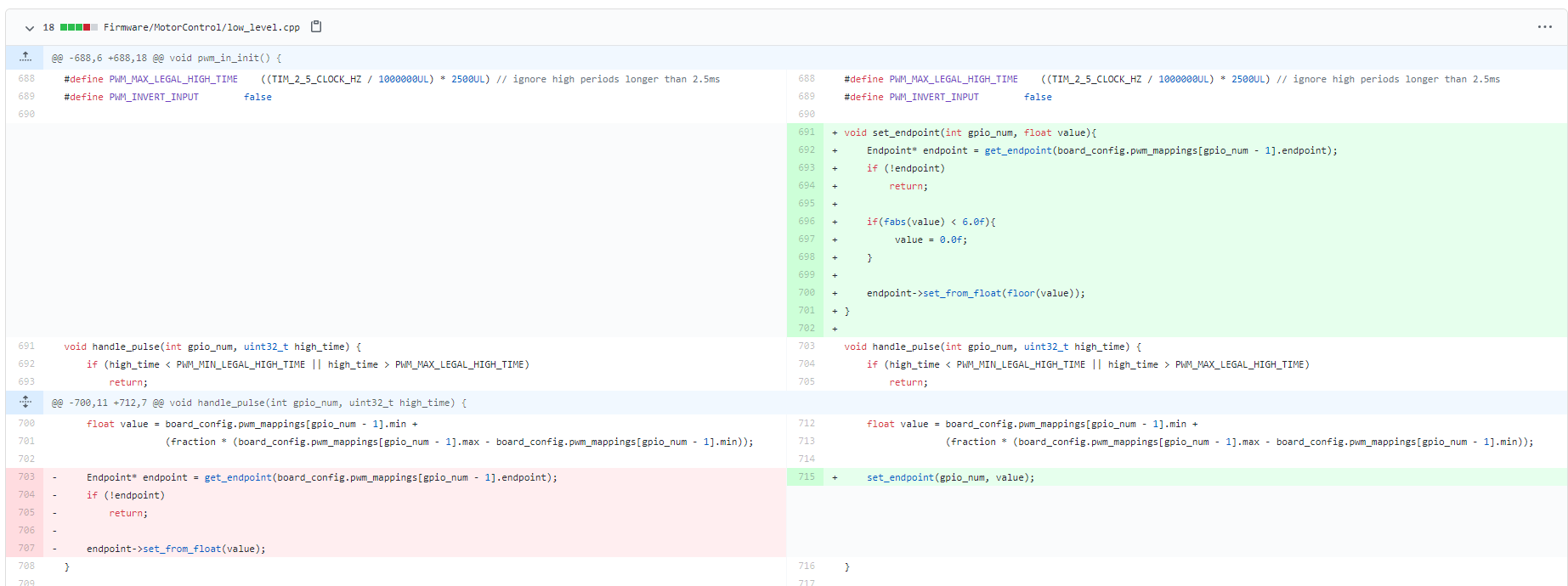
Yes, sure. The issue is that the PWM signal when it is measured on the ODRIVE side is not exactly 1500, but 1500.001 for example. I’ve changed the firmware by introducing dead zones of + - 6 around 1500.
Then don’t request it over the interface?
If all you’re doing is driving a “robot wars” style robot, i.e. a glorified RC buggy with thumb stick controllers and a radio, then sure, you will never need this information. Congratulations on your purchase of a very expensive ESC.
My point is, PWM is both inflexible and imprecise. A dead zone is a hack, and it’s only useful for manual control. If you’re trying to do real robotics with automatic control, then PWM is a very poor choice of interface. And if you have something like an Arduino that is capable of using the more intelligent communication interfaces, then really there is no excuse for PWM, it’s just lazy, and will come back to bite you.
My robot is real and worked whole summer on golf field. I DON’T need any info from ODRIVE because I’ve got very precise localization system, so software know when and why it should set PWM signal without any info from ODRIVE. ODRIVE isn’t only very expensive ESC - it’s work as wheel damper on grass and rough terrain, thanks to very fast and reliable PI controller. Also for another indoor robot I wrote ROS package with USB ODRIVE native protocol including temperature, ststus, current, odometry, etc. But this is another kind of robot. If you got 2nd PID whith external localization you just DON’T need any info from ODRIVE.
Good for you!
But when the customer asks “How do I get the drive temperature, or the battery voltage?” Or “Why did my golf trolley catch fire when it got stuck in the sand bunker?” you will say “Because I made a lazy design decision”
Yes of course- it depends on what values you get from the bluetooth link. e.g. If it gives you between -1 and +1 then you simply multiply by your intended max speed.