I have an Odrive 3.6 and a D6374 motor. I have these connected to a test rig with a 1m linear axis and a 2kg mass. I’m powering the odrive with a 48V, 50A power supply.
When I try more aggressive accelerations (e.g. >400 rev/s^2) the axis will often accelerate then coast to a stop, and if I do a dump_errors() I see:
system: no error
axis0
  axis: no error
  motor: Error(s):
    MOTOR_ERROR_UNKNOWN_TORQUE
    MOTOR_ERROR_UNKNOWN_VOLTAGE_COMMAND
  sensorless_estimator: no error
  encoder: no error
  controller: Error(s):
    CONTROLLER_ERROR_SPINOUT_DETECTED
What could be causing this? Could I be exceeding the maximum current my supply can provide, and would that cause such a problem? I was having a problem with noise affecting the USB connection to the odrive which I seem to have resolved with a ferrite ring on the motor cables, but could this be another manifestation of the same problem, e.g. interference on the encoder lines?
Also I have a couple of questions about the trapezoidal trajectories:
Is there a state I can read which will tell me when the trajectory is complete?
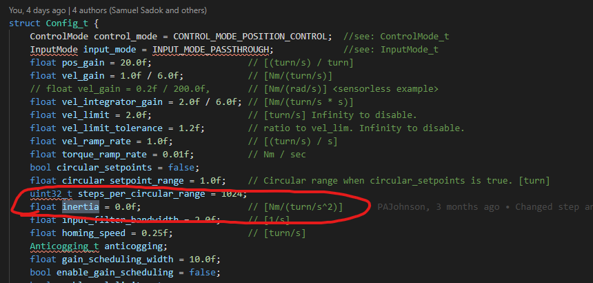
What’s the purpose of the inertia setting? I’ve done some calculations to estimate (for a given motor torque), and known the system mass, inertia and friction, what acceleration I can expect, and this is what I enter as the trap accel/decel values. Does the inertia value affect the gains in the controllers?
Finally, is there a way the odrive can brake the motor if it enters an error state, rather simply letting it coast to a stop?
I disagree. There are other drives which achieve this by shorting (or PWMing with a fixed duty cycle) all phases to GND in their equivalent Idle state.
Point of terminology btw: What I described is different from what I understand “plugging” or “plug braking” to be.
“Plugging” is where you apply a voltage 180° out of phase with the back EMF - i.e. both the back-EMF and the applied voltage contribute to the rate of change of current, so you can change the current twice as fast as a dead short would, and potentially you could reach an instantaneous current of nearly twice the stall current at 100% PWM. It’s an extremely violent thing to do to a motor.
What I am talking about is non-regenerative dynamic braking, i.e. the worst it will do is short the phases together, and if we apply a PWM duty to that shorting, it can do it in a controlled way, and you don’t need any commutation info to do this.
It’s a physical property of your system, not the controller. Specifically the total inertia of your system, which will be the angular inertia of any rotating components (i.e. your motor, shafts etc) + the mass of any components doing linear motion, expressed as an inertia. I’m presuming the units are kg m^2. At least, following this method for my system, I’ve noticeably increased the performance when doing trap moves with high accelerations (previously the velocity was overshooting slightly, and I didn’t have very square corners in my velocity v time plot).
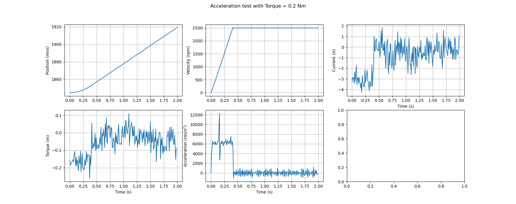
I know the mass of my linear carriage (1.9kg - measured with a scale). I also did an experiment to measure the D6374 inertia, by applying a 0.2Nm torque with nothing connected to the motor (except encoder and tiny pulley) and measuring the acceleration, the inertia can me calculated as follows:
inertia x angular acceleration = torque
=> inertia = torque/angular acceleration
= 0.2/(2500 * 2 * pi/60 / 0.41) = 0.0003 kg m^2 (see plot below for these values)
My carriage is moved by a pulley with pitch radius 9.55mm. So I can work out my total inertia:
system inertia = 1.9 * 0.00955^2 + 0.0003 kg m^2
You could also just try accelerating your whole system with a known torque and using the first method to work out the effective inertia. Hope that’s some help. If not I suggest googling moment of inertia.
It’s actually in newton-meters per (turns/s^2) [Nm/(turns/s^2)] lol. This is because the trapezoidal planner is in terms of turns, turns/s, and turns/s^2. So
turns/s^2 * (Nm/(turns/s^2)) results in Nm of torque command.
Another question about trap moves: I want to both calculate and measure energy consumption when doing a trapezoidal move, including the braking phase.
I’m not really sure where to start with the calculation - I know the torque constant and torque, so I can work out the current during acceleration. Can I then just use the winding resistance to figure out power (i.e. I^2*R)? I suspect it’s not that simple. Then I’m not really clear what’s happening during the braking phase - are we simply taking energy out of the system and dumping it in the braking resistor, or are we putting current through the windings to actively brake the motor? I.e. do we actively consume power from the supply when braking? I’ll settle for a ballpark calculation, it doesn’t need to be super accurate. But I would like a decent estimate of energy consumption for different trap moves (accelerations, peak velocity and distance) for a given motor.
Then what’s the best procedure for measuring the actual power consumption on my real system?
Some current is being burned in the windings because the phase current (Iq) goes negative to brake.
No, it’s more like the stored rotational and magnetic energy in the motor is removed (negative current) and turned to heat in the brake resistor. The power supply current ideally goes to 0 during braking.
Measuring through the power supply would be best. Otherwise… probably (odrv0.Ibus + odrv0.brake_current) * odrv0.vbus_voltage, except I think the brake current value is only in 0.5.3 development branch right now.
Ok, thanks for all of that. But given that I’m not consuming power from the supply in the braking phase, presumably
odrv0.ibus * odrv0.vbus_voltage
should give me my power (from the supply)?
And do you have any suggestions about how I can do a calculation to predict energy consumption?
Re controller bandwidth, I’ve been doing trapezoidal moves and logging a bunch of variables to produce plots. I’d been logging at about 100Hz and bumped this up to 200Hz to get more accurate plots. But I realised that sometimes I was spending too long in the loops (at the end of the logging loop I set the time to next pull the data, and I can see that that time has already passed), so I wondered if polling the odrive so fast was impacting its performance. So I dropped way down to 25-50Hz, and then found that I could command faster accelerations (for a given bandwidth) without getting errors. I.e. it seems that polling the odrive so frequently for data was affecting the controller performance. So, I guess the question is, does this sound right, and is there a more efficient way of pulling the data off the odrive? Currently I do commands like pos[index] = axis.encoder.pos_estimate, and I’m grabbing about 10 variables every cycle.
Re the inertia, if I have T = I * angular acceleration, then I has units Nm / (rad / s^2) (which presumably are the same as kg m^2, but I can’t see how to get from one to the other right now). Anyway, I make it that multiplying my inertia value by 2*pi will give me inertia in Nm/(rev/s^2). Doing this gives me even ‘neater’ trapezoidal trajectories, so it seems like I’m on the right track.
Just to add, for the energy consumption calculation, I’m happy to ignore the coasting phase, and if it’s correct no energy is consumed from the supply in braking, the braking phase too. So basically I want to calculate the energy use while doing constant torque acceleration up to a max velocity, for given motor and load.
Ah yes, you’re right, I misread the code and I can see that Ibus (as reported in odrivetool) is already taking the brake current into account. So just Ibus * vbus_voltage will work fine.