Hello Fellow ODrivers,
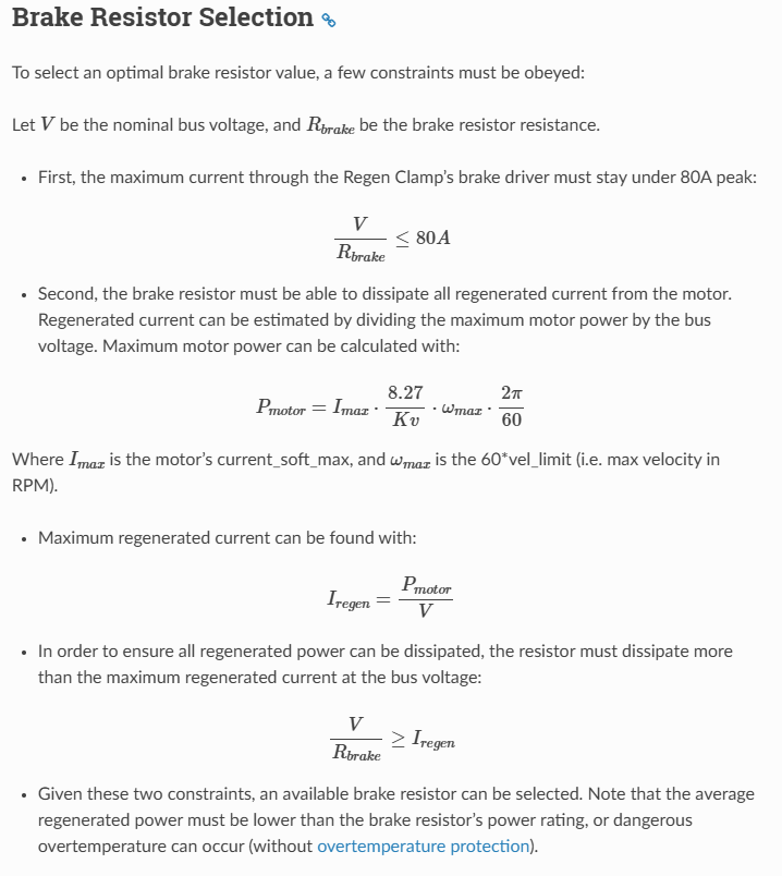
I wanted to know how I should proceed with calculating my regen clamp resistor bounds as shown below (from the regen clamp data page) using four ODrive S1 connected to four D5065 270kv respectively. It feels like I would need to multiply or divide by four somewhere but would love some guidance.
My amperage is limited by my 24VDC 40A power supply. I would like to stay below 38A while operating if possible. All of my motors will be connected to different gear boxes but my the motor with the highest RPM will be around 6000RPM. With that info, I ran through the calculations and came up with a resistor value range of 0.3Ohm <= R <= 0.788Ohm. Is this right?
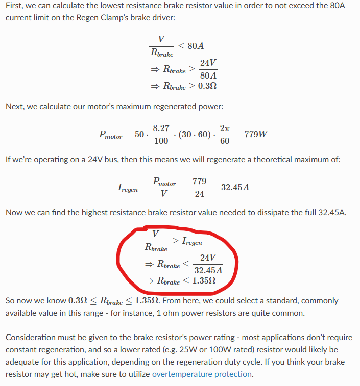
On another note, just to be thorough with my calculations, is this final step a mistake on the regen clamp datasheet page? Should it not be 0.74 Ohm for the upper bound?
Thank you and hope to hear back soon,
Emi
Hi Emi,
Thanks for the question! Assuming the cumulative regenerated current of all four ODrives will not exceed 38A, then that would correspond to a maximum resistance of 24V/38A = 0.63 ohm. As maximum regenerated current is usually quite a bit lower than supply current (given motor efficiency/inefficiency), I think this is a safe bet. You can also limit the per-ODrive regenerated current via the active power limit feature, namely I_bus_soft_min.
And yes, you’re right – docs are wrong! I just fixed that, should update in a few minutes.
One more note – the regen clamp is happy to let the bus voltage float higher if Vbus/Rbrake < Iregen. So for instance, you could use a 0.5ohm power resistor, and limit the S1s to a ~40-41V overvoltage trip threshold. Now if all ODrives regenerate at once, the bus voltage will be able to float up to 40V or so, corresponding to a peak of 80A current dissipation in the brake resistor. And generally given motor inefficiency, I’d imagine this should be an adequate amount of regenerated current handling for all four ODrives, unless you envision simultaneous full-torque braking from the motor’s absolute maximum free speed (which is when maximum current is regenerated) across all four ODrives.
Hey solomondg,
thank you for the response. I do not think I will be doing a full torque brake but I so have an E-Stop in my system that cuts power to the regen clamp if pressed. This I imagine will dump all of the energy into the regen clamp. My current concern is that I will need to find a 0.5ohm resistor capable of handling ~40A which comes to roughly 800Watt resistor. I think something like this would work but it is fairly expensive.
The 800W rating is continuous, you only need pulsed power. Usually those big wirewound resistors have a real good amount of thermal mass. So something like this should work just fine (albeit maybe get a bit toasty - don’t touch!). You can also get some way chunkier ones overseas for the same price – e.g. here’s a 450W rated 640mohm one for $19: VO RX24/450W-0Ω64±5% Pinout Diagram & Footprint Diagram | LCSC Electronics
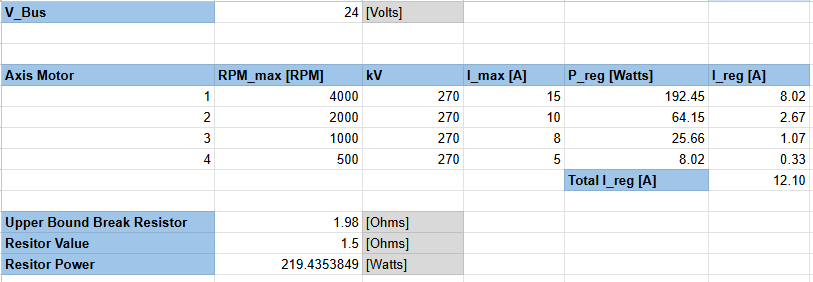
Reran the regen clamp resistor calculations on each of my motor separately, added the results and found an upper limit for my resistor:
I think I can get away with a 1.5ohm resistor rated at 250W, specifically this one.
Let me know what you think and with your blessing I will be good to move forward. Thanks!
Sure! I don’t see an issue at all. I’d maybe get a 1ohm just for more headroom, but I’m sure it’ll work fine 
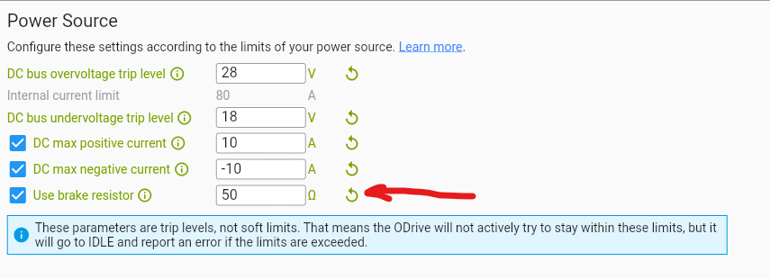
One last question on this front. When configuring my ODrives, what break resistor value should I use? Does it have to be some fraction of the total resistance as per the maximum current that the axis should experience or is it just the 1.5ohm value for all my axis?
If you’re not connecting the brake resistor directly to the S1, you should leave that box unchecked.
1 Like