Need clarification difference ODrive <> normal stepper driver

I have a bunch of issues which i am going to address in different posts, but for now i need some clarification on the difference between how ODrive does position control compared to a normal stepper driver.

A normal stepper driver uses a “steady” current and rotates the electromagnetic field to the desired angle. So the amplitude of the current doesn’t change, the position is only set by the rotation.

As far as i understand (which might be wrong or just too incomplete) I assume the ODrive does the FOC/position control in 2 parts:

  1. rotate the electromagnetic field (and compensate/optimize I <> V phase shift --> FOC stuff)
  2. adjust the current according to angle/setpoint deviation --> PID-part

So the ODrive rotates the electromagnetic field to the desired position and if there is a setpoint deviation it cranks the current up via PI-loops.

Is that correct ? I am trying to understand the PI(D)-loops (https://docs.odriverobotics.com/control.html) but it is unclear to me how the position/angle is set ?

Not really it’s more like this

  1. At a low lever FOC allows us to exert as much torque as we want fairly accurately, by controlling the current, because torque is proportional to current

  2. After this you can consider the position controller and velocity controller in that diagram as doing similar thing. According to the error in position or velocity it calculates how much torque it should apply in reaction

So if the motor is already in position it applies no power, if the position deviates it applies a torque in the opposite direction bringing it back and forming a closed loop control system

Steppers/drivers use the direction of electromagnetic field directly because they have no feedback and thus no way to do closed loop control like the odrive and because steppers are designed such that this works with enough ease and resolution

A brushless motor could theoretically be locked in position in the same way a stepper driver does but brushless motors usually only have 14-28poles while steppers have 100s and it would be incredibly inefficient as current must always flow even when there is no external force or deviation. A stepper is designed such that low current can produce a decent amount of torque, while sacrificing speed. Brushless motors are usually the opposite

Thanks for your answer. Unfortunately i have some problems to understand it. Maybe i should go more into detail of my understanding.

The main handle for torque is always the current in the coil - that is clear. FOC optimizes the I <> V phase shift to increase efficiency, therefore it needs the position and we need some encoder. Afaik FOC is not responsible to set the “amplitude” of the current. FOC “only” optimizes the phase positions and the phase shift between the voltage sine wave and the current sine wave in order to let the electromagnetic force to pull in the optimal (max torque) direction. The rotation speed of the electromagnetic field is set, so it is an input and no output. The output is the voltage curve to get the needed current sine wave to achieve the max torque at the desired rotational speed. E.g. in steady state the V<>I phase shift is zero. At higher revs one has to compensate for inductance, back EMF and so on, therefore the phase shift increases.

That is what i summarized under 1. This part can only be done by the “inner current loop” and should have in principle nothing to do with velocity and position control. They come on top.

So we need something that sets the current amplitude, that should be done by the velocity/position control loops. This is what i summarized under 2.

Is the above correct ?

I know that FOC is efficient and not doing more than “needed” and the difference about open and closed loop.

One of my problems is, that i try to use ODrive with step/dir in position mode and that the ODrive solution is not competitive at all. This has several reasons and the most important is the bandwidth of the whole system, especially the control loops.

In order to be able to think about how to improve the overall bandwidth, i need to know which part does what…

If it works like described it should be easy to increase the bandwidth dramatically by adding a feedforward current. So ODrive is not allowed the adjust the current from 0-100 %, it is only allowed to utilize the range from 80-100 %.

This is clearly less efficient in terms of waste heat, but 1st comes performance ! Once the performance is ok, one can decide how much heat should to dissipated…

If I understand it correctly, FOC ensures that the current vector phase and magnitude is correct in the d-q plane.

The current control loop is tuned for a bandwidth of 1kHz, by default. The system response is of course bound by the overall inertia.

Servos don’t work like stepper motors, you can’t apply a holding torque with no load - applying a current will just make it accelerate.

Can you expand on this? Maybe we can help you find a solution? For instance, we have an experimental branch that can take step/dir pulses and generate velocity and current feedforward terms.

Thanks for your reply.
ODrive is in general awesome, there is nothing comparable out there. It is made for high power applications which less demand on trajectory “smoothness” and accuracy.

But ODrive is only one way of solving problems. There are also others e.g, NEMA steppers with stepper drivers (open loop). This is clear on the other end - low rev and high torque, but anyhow we need to push the limits and i try to use ODrive also for typical stepper applications like FDM and CNC. I will go into detail in other posts. So lets come back to this thread.

The current control loop is tuned for a bandwidth of 1kHz, by default. The system response is of course bound by the overall inertia.

It is 1000 rad/sec (about 159 Hz) and the limitation is not the inertia (in my case), it is really the bandwidth limited by the control loops - which is in the end defined by the PID gain values. If the velocity is the master of the current loop, it cannot have more than 159/10 - 159/5 = 16-32 Hz in a robust way. Faster would only work reliable in a lab under academic prerequisites. Adding another cascade for the position loop can´t make it faster, even the position loop is only a P-loop. This is also what i see when testing.

Servos don’t work like stepper motors, you can’t apply a holding torque with no load - applying a current will just make it accelerate.

That is one reason for my questions ! If the FOC only sets the voltage (and by that current) sine waves to get the desired position, you can apply whatever current you want to, it doesn’t accelerate - it just produces more (holding) torque and much more “bandwidth” ! That is the point ! In my understanding the FOCs sets the position/direction of the forces/currents but not the magnitude.

Respectfully, your understanding is wrong

you say FOC only sets whatever to get the desired position, that’s just wrong. It applies a current to create a stator magnetic field 90degrees from the rotor permanent magnetic field which produces torque. A torque that pushed the rotor and makes it start spinning

You see what happens when you apply the stator magnetic field is it applies a torque to align the stator and rotor magnetic field, if you don’t change the stator magnetic field like a stepper driver, the rotor will eventually align with the stator. FOC doesn’t do that, it keeps rotating the stator magnetic field to stay 90degrees from the rotor and achieve maximum efficiency

So applying any torque WILL accelerate the motor, you cant just increase current and increase “holding torque”, which is a lie anyway, a standing still stepper produces no torque, just like a closed loop brushless, torque is only produced when there is a small deviation that misaligns the stator and rotor as that is the only time magnetic force is exerted. The difference between odrive and stepper is when no torque is needed no current is consumed and the exact strength of how it reacts to deviation is tunable in software

You want more “holding torque?” You don’t apply a demand a constant current to FOC that’ll make it spin away, you increase the gain parameter so it applies more torque when needed to correct the errors

You want more bandwidth? Also increase the gain up to the point your system inertia allows it. But your calculations about the bandwidth don’t make sense to me so I don’t really know what the problem you are facing is

Thanks really for your reply. The reason why i am asking is because i don´t know it :wink: As a “scientist” i am trying to understand things and therefore if i have a “problem” to understand something i ask again… in hope that somewhen i get the point !

you say FOC only sets whatever to get the desired position, that’s just wrong. It applies a current to create a stator magnetic field 90degrees from the rotor permanent magnetic field which produces torque. A torque that pushed the rotor and makes it start spinning

Could you please explain how FOC works when nothing spins e.g. steady state setpoint control (loaded or unloaded, doesn´t matter) ?

In my understanding FOC just sets the “orientation” of the magnetic field to the desired position and applies the given magnitude of current. One step is to get the 90 ° and the other step is to apply the needed voltage <> current phase shift to get there. If nothing rotates, voltage and current are in phase. In this case FOC behaves like a stepper motor driver (until the rotator is moved, or is moved so little the FOC can´t see it) and for sure no deviation means no torque. And because of that it is no problem to apply a current without anything spinning. The spinning comes from rotating the magnetic field. If the magnetic field is not rotating why should the motor spin ???

In my thinking the FOC part is strictly separated from the position/speed control part.
The efficiency increase of FOC does come from orienting the magnetic field properly (90 °), not from having no current. Having no/less current comes from the outer loops (velocity and setpoint) - if this is correct or not is one main topic i have to figure out to understand it.

You want more bandwidth? Also increase the gain up to the point your system inertia allows it. But your calculations about the bandwidth don’t make sense to me so I don’t really know what the problem you are facing is

I work in the industry and PID-loop tuning is part of my daily job. I would assume i am not doing it worse than the average ODrive user :wink: Believe my, the tuning is as aggressive as it can be and the inertia is no problem at all.

The control schema shown in the picture above defines 2 cascades.

  1. The position loop defines the setpoint for the velocity loop.
  2. The velocity loop defines the setpoint for the current loop.

A cascade one and only can work if the slave (e.g. current loop) is by far much faster than the master (e.g. velocity loop). That means before the slave gets a new setpoint, the old setpoint has already to be reached (reasonable). Otherwise it will oscillate ! If the slave is 5 times faster than the master, it will very likely work. 10 times faster and it will work in a very robust manner. In industry some would aim for 20x. This cuts our bandwidth down a lot if you have cascades in cascades like here.

A PID-loop is linear and by that assumes a constant plant. In a lab it is possible to ensure “linear” relations, but not in real life. E.g. when the motor heats up, your process gain changes already…therefore a reasonable margin is needed, or it will work sometimes and sometimes not.

@vatpom
Firstly, your understanding of a stepper motor is wrong. A normal stepper motor driver does not ‘orient’ any magnetic fields, it only needs to change polarity to execute one step.
See https://www.applied-motion.com/news/2015/10/how-does-step-motor-work

Most stepper motors are ‘reluctance’ steppers, which have little teeth on the poles. The teeth form the magnetic circuit between rotor and stator, and as with any magnet and iron, will pull tightly together if they are closely aligned, but only loosely if they are not aligned. The ‘holding torque’ comes from the force that is necessary to break that magnetic circuit once established.

Other steppers include “can-stack” steppers which are even simpler in construction - they have no wound poles! The ‘teeth’ in this case are connected to alternate sides of a single coil, and there are permanent magnets on the rotor.
https://www.allaboutcircuits.com/textbook/alternating-current/chpt-13/stepper-motors/#02452.png

‘microstepping’ can be applied by some stepper drivers to get extra resolution between steps, by energising both coils at different relative magnitudes simultaneously - essentially trying to hold both positions at once, but with different forces. Microstepping only works if the static load is essentially zero, e.g. driving a worm gear, or a leadscrew on a 3D printer

This is sort of similar to what FOC is doing, but still very different. Stepping (including microstepping) is completely open-loop. It has to assume that there is no load torque and that the rotor will align itself with the magnetic field, which it won’t if there is a load. Actually, when the ODrive is working in its open-loop mode e.g. for index search, this is also known as microstepping, because it’s the same thing at this point. But this is not FOC.

FOC itself is closed-loop - it needs to know the ACTUAL rotor angle, so as to align the field against the magnets at all times, even in the presence of a load. That’s why it is more powerful and more efficient than microstepping, because the field is aligned to the optimal torque-producing angle, and because the magnitude can be adjusted to whatever is needed to apply the desired torque. Stepping and microstepping drivers need to apply a high currrent at all times because they don’t know where the rotor is, and have to assume that it hasn’t skipped a pole.

You are correct that this is only to do with producing a torque - velocity and position are controlled by the outer PID loops.
Steppers are inherently velocity-driven, and have no control of torque whatsoever. But even at zero velocity, steppers drive their full current and continue to get very hot.
FOC is inherently torque-driven. At zero torque, FOC drives zero current.

@towen
The following sentence is the key for me:

FOC is inherently torque-driven. At zero torque, FOC drives zero current.

THANKS, I think i found my misunderstanding: the desired current is the input and not the desired angle position. FOC keeps always the 90 °. The given current produces torque and the outer loops adjust the current to meet position and/or velocity in the end. Therefore the FOC stuff itself as is cannot produce a holding torque.

The problem here is that without PID-loops nothing happens and the limited bandwidth of the loops makes it worse than open loop NEMAs for FDM applications.

To get holding torque comparable with normal stepper drivers, we have to increase the part of current which only makes waste heat - this current doesn´t rotate anything but as soon as the angle changes it produces torque without delay, like normal stepper drivers. This decreases efficiency, but gains bandwidth. 1st comes performance and 2nd efficiency.

To increase the bandwidth we need to get more open-loop into the closed-loop, therefore i wanted to apply a base current. Open loop means maximum possible bandwidth. I will show what i mean soon.

Oops you’re right! Nevertheless, this is configurable via
<odrv>.<axis>.motor.current_control_bandwidth (I wouldn’t go much higher than 2000)

Bingo. Well, this is how ODrive is configured currently. You can also optimize for saliency and / or field weakening above base speed

Oh, yeah, we could have told you that. For FDM (low speed, for a servo), you want a very high resolution encoder to get very tight position and velocity feedback, and you probably want to use our anticogging algorithm to remove the cogging torque as much as possible. Better yet, throw a 10:1 gearbox or higher on the motors to get them to run at higher speed. Servo power comes from speed, not necessarily low end torque. And you’re going to want to feed proper trajectories into the position with velocity & current feedforward terms. Step/direction as implemented in the master branch doesn’t do this, but the INPUT_MODE_POS_FILTER setting in some of the development firmware does. If you set a system inertia, it should also generate current feedforward term

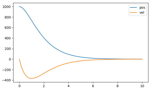
secondOrderResponse

You can try the RazorsEdge branch if you want CAN, Endstops, homing, and the “input filter” functionality shown above. https://github.com/Wetmelon/ODrive/tree/RazorsEdge

Thanks again.

I can´t set the current bandwidth reasonable higher without getting unstable. I tried that already. As well as cranking up gains close to instability.

I am using AMT CUI 8192 cpr encoders and could upgrade for the 8192*2 types, but i would say i need a factor of > 10x … and increasing encoder resolution only helps if the ratio to noise and latency (e.g. encoder built in averaging) doesn´t get bigger. I found 16 Bit encoders (the one ustepper uses), which should be in the end worse than the 13 Bit CUIs.

I have tried anti-cogging but as long as the cogging map cannot be stored it has no practical usage for me and even with anti-cogging, it could not outperform the cheapest open loop NEMA solution by far.

From my test i know, that gearing doesn´t really help - at least not without feedforward active. Because the motor has to spin/accelerate even quicker the bandwidth limitation acts even worse. So you don´t gain anything, but you run into the rev limit of the encoders/BLDCs/construction. And gearing could anyhow only work without backlash and other nonlinear torque stiffness effects.

I did not compare only RC BLDCs on ODrive with 2 phase open loop NEMA steppers (which are just 2 phase BLDCs as we know), i also compared 3 phase NEMAs on ODrive with open loop NEMA steppers. The result is always the same, because of bandwidth limitations and cogging issues the open loop NEMAs are always much better - also on “higher” speeds for high pole count NEMA steppers like > 20 revs/s.

Interestingly also a 3 phase NEMA stepper has cogging issues with ODrive, although it is clear that the cogging itself (without FOC, PID stuff) cannot be the problem, otherwise it could not work better when driven in open loop…

The feedforward terms should help a lot. Where do i find the RazorsEdge .hex files for a v3.6 24 V ODrive ?

Like i have mentioned already it is clear that ODrive aims for a different area. But either we find a way that ODrive is able to outperform also cheap open loop NEMAs for FDM and so on, or we have to clearly communicate where ODrive is a waste of money and time…

Er no, as I tried to explain above, a stepper motor is NOT the same as a PMSM (aka BLDC motor).
BTW, “NEMA” does not standardise the type of motor, it only specifies the mechanical mounting flange and physical dimensions. You can get many different types of motor in the same NEMA form-factor.

Odrive is NOT designed for stepper motors, that’s an experimental feature at best.
I repeat, Permanent-Magnet Synchronous Motor != Stepper Motor.

The advantage of a FOC-controlled PMSM is always for closed-loop. It is simply stupid to try to use it open-loop. Yes, steppers are good at precise positioning of very small and well-known loads at low speeds, however the positioning bandwidth of a FOC-PMSM (despite the nested control loops) will definitely outperform a stepper motor for large moves and anything with a variable load, because a stepper has such a nonlinear torque response.

But honestly, I don’t think ODrive should have a step/dir interface at all, because anyone using such a simplistic interface is not going to see the benefits of this motor controller…

Seriously? That’s a bit rude. This is an open-source project, not a commercial company. Also, nobody was ever claiming that ODrive is meant for “no-load” applications like FDM. It is for high power (speed * torque) applications like robotics. Yes, like the demo video, it can also be used to make a really, really fast CNC router, but don’t expect super high accuracy unless you have the expertise to implement it yourself using the existing code as a base.
For example, if you were to use a 10:1 timing belt drive, with dual encoders (one on the motor and another on the load shaft, ideally at the other end of the leadscrew) you could implement extremely precise and fast control. But you would need to delve a bit into the firmware to achieve this.

There are no .hex files provided for RazorsEdge. You need to compile them yourself, and unless you are comfortable and competent in doing this, I wouldn’t recommend it.

You keep talking about the bandwidth restriction but I don’t understand why it’s relevant. What are you actually trying to accomplish? Load holding? That doesn’t make any sense in an FDM, since there is little to no external load.

This is really starting to feel like an X/Y problem…

BTW, industrial servos usually use encoders in the millions of counts to achieve extremely high stiffness. 8192 is woefully insufficient for that.

You can save the anticogging map in RazorsEdge, and it even allows you to use a separate encoder for positioning vs commutation if you want to do that.