found it out a minute before your reply, thank you very much!
Now i’m back to the weird behaviour talking about before…
With regards to tuning, you should start off in torque control and work your way up from there. If the motor operation is not smooth in torque mode, the other modes will struggle, as they’re just nested control loops.
Set all gains to 0, and controller.control_mode=CONTROL_MODE_TORQUE_CONTROL
Set input_torque to zero and go to closed loop
You might hear something out of the motor, but it should turn freely by hand.
Then carefully hold the motor and change the input_torque to 1. You should feel a slight pull in one direction, which shouldn’t change much as you continue to move it around by hand.
Then you can go to velocity control and slowly increase vel_gain until you get good speed control, etc.
Ok nice, thank you for your instructions. I did as you described:
odrv0.axis0.controller.config.control_mode = CONTROL_MODE_TORQUE_CONTROL
odrv0.axis0.controller.config.pos_gain = 0
odrv0.axis0.controller.config.vel_gain = 0
odrv0.axis0.controller.config.vel_integrator_gain = 0
odrv0.axis0.controller.input_torque = 0
As you described, i hear some little noise out of the motor, but nothing is moving. Then i turned it manually to see if there is any force against it, and then Axis, Motor and Controller went into error:
Motor.Err: ERROR_CONTROL_DEADLINE_MISSED
Controller.Err: ERROR_OVERSPEED
I guess that’s normal because i manually “forced” the controller to leave his setpoint.
EDIT: i now see, that these errors come already without manually interfering, after like 5-10 seconds. That feels wrong! What am i doing wrong?
It seems that these errors do not automatically appear after the same time, it looks like a random appearance. I now had a run without that error, was holding the shaft, did not feel anything. Increasing odrv0.axis0.controller.input_torque did not change anything in the motor behaviour, could not feel any pull at all. Increased it to 1, 2, 3, 4, 10, 100 without any change… That is now the original problem of my post (see top). No force at all…
It sounds as if your Hall sensor is being interfered with by noise… Although I would have expected you to get ERROR_INVALID_HALL_STATE in that case…
You would get ERROR_OVERSPEED if the motor runs away, or if you somehow manually turn it faster than controller.config.vel_limit.
You can ignore CONTROL_DEADLINE_MISSED - it is caused by the overspeed error.
Make sure controller.config.input_mode is set to INPUT_MODE_PASSTHROUGH
Checked controller.config.input_mode, it currently is 1 what matches INPUT_MODE_PASSTHROUGH, so that should be ok.
Regarding the noise: is there any possibility to make that situation better? I will now try to shorten the cables and increase the distance to the motor cables. Is there anythin else i can do?
Shortening and/or braiding the motor cables should help, so should shortening and/or twisting the power supply wires. Some people (including myself) have found that adding 22nF capacitors between each of the Hall sensor inputs and GND also helps a lot.
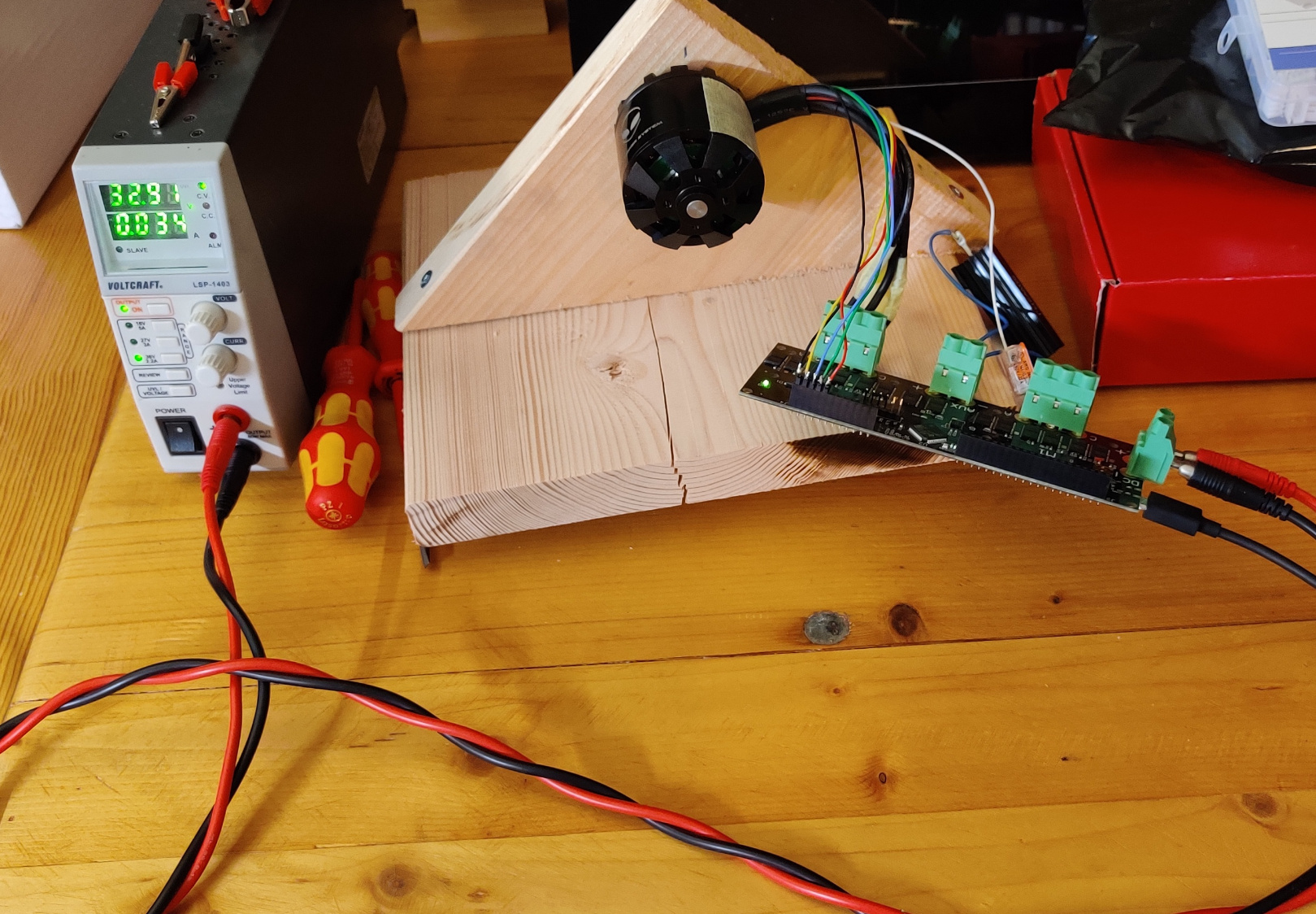
Here you can see my current setup:
Actually all cables are minimally short, i couldn’t make them any shorter to be honest.
How did you add the capacitors? Is there a location on the ODrive PCB or did you attach them to the cables directly?
Also: when increasing input_torque, should i be able to see an increase in current drawn from my power supply?
I carefully soldered them to the back of the ODrive PCB itself… I twisted the three ground legs together and soldered them to the GND pin at the back of the encoder header, and then soldered each remaining leg to the A,B,Z pins.
Yes, you should see a small increase every time you increase the torque. It won’t be as much as the motor current itself, but it should be very noticeable.
What values did the ODrive measure for motor.config.phase_resistance and motor.config.phase_inductance? Do they match your motor’s spec?
You could try increasing motor.config.calibration_current if you have a very low resistance motor.
I will try to add the capacitors, but i have to order them first, unfortunately…
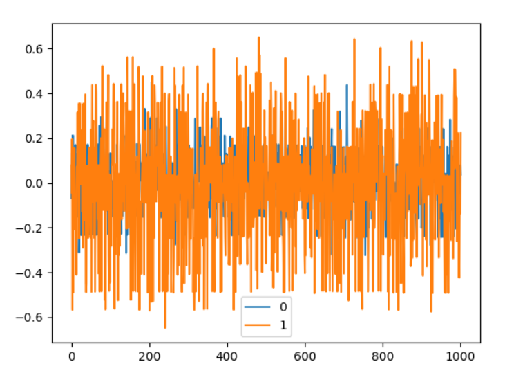
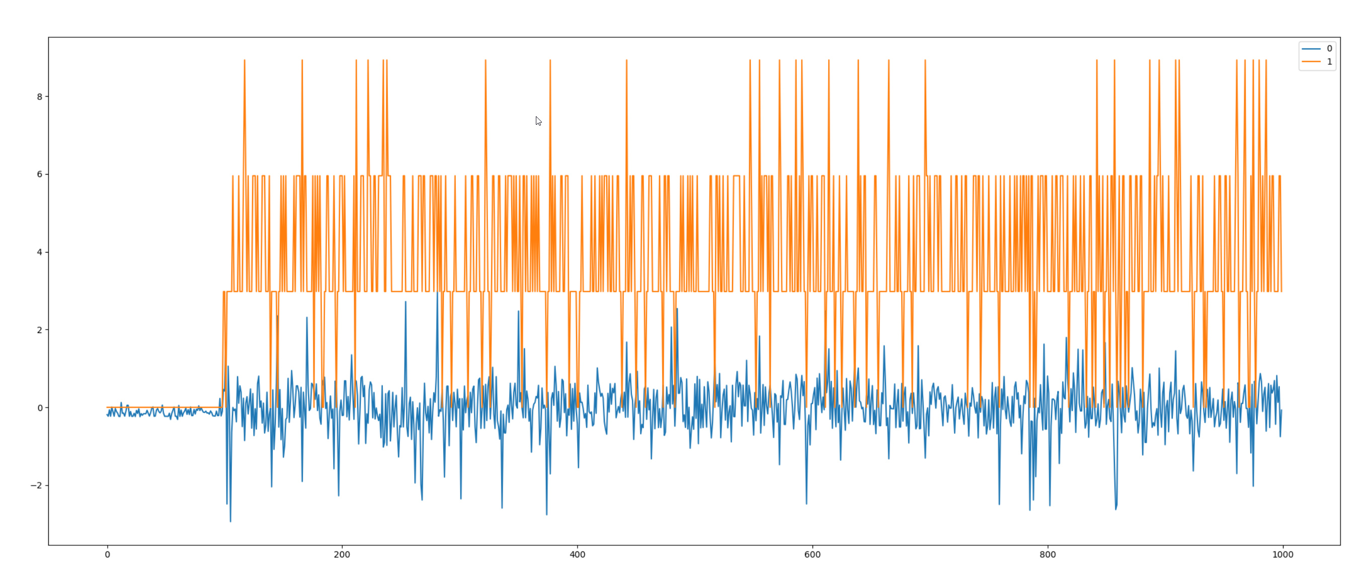
I can’t see any increase in current during closed loop control in torque control mode. The power supply tells me, that 68mA are drawn, regardless of if i command 0, 1, 3, 10 Nm of input_torque. Interestingly, during calibration run, i see around 400mA on the power supply. The liveplotter also tells me, that no current is drawn at all, see the following scope during a time input_torque was set to 3:
phase_resistance = 0.08205939084291458
phase_inductance = 3.98140364268329e-05
My problem is, that i do not exactly know which motor i have here at the moment, because i am using a motor of my colleague. I will tomorrow try to get a better datasheet, all i know at the moment, that it’s one of the motors listed here.
My motor.config.calibration_current is set to 10A at the moment, as said before, i can see 400mA been drawn during calibration.
Yes, it’s normal to see 400mA being drawn from a 30V supply, when pushing 10A through a resistance of only 0.08 Ohms, since i^2 * R = 100*0.08 = 8 Watts.
400mA from 30V is… 12 Watts.
So after erasing config, you are still unable to drive the motor in torque mode? Very odd…
What config items did you change to get to this point? Just polepairs and cpr?
Just to check, you do have encoder.config.type = ENCODER_TYPE_HALL, right?
With a current_lim of 10A and torque_constant of 0.04, the maximum torque you can command is 10 * 0.04 = 0.4Nm. Everything above that value will be limited internally to 0.4Nm (the limit is the lesser of torque_lim and current_lim * torque_constant). It is strange that the power supply current would not increase to a value over 68mA when you command a non-zero torque.
1 Like
0.4Nm is still quite a lot of torque for an unloaded motor not to be turning. It’s about the weight of a pint of beer on the end of a 15cm ruler. 
It seems to me that @moaeX29’s ODrive is not sending any current to the motor in torque mode. As I say, if it really is driving 10A in any direction, he should see the same 400mA on his power supply that he sees during the calibration process. Something fishy is going on.
Thank you for your help, i really appreciate that!
@towen: these are the commands i set after erasing configuration:
odrv0.axis0.encoder.config.mode = 1
odrv0.axis0.encoder.config.cpr = 42
odrv0.axis0.motor.config.pole_pairs = 7
odrv0.save_configuration()
odrv0.reboot()
So yes, encoder type is set to Hall. No other changes than that. Complete calibration run works without errors.
@PJohnson: thanks for that hint. At least now i know, that it can’t make any difference if i command 1, 2, 3, or 100 Nm, because it’s limited to 0.4, if i understood correctly?
Generally speaking: could it be a reason for all these problems if i mixed up some wires to the motor / encoder? I didn’t have any document for my motor, so i just mixed the phases until the calibration run was successfull. I felt save with the successfull calibration run, but maybe there are some cases where calibration run succeeds but it still isn’t the right configuration?
P.S. when exiting odrivetool, i almost always get error logs like this:
Exception ignored in: <function Image.__del__ at 0x03F28F10>
Traceback (most recent call last):
  File "c:\users\maxdh\appdata\local\programs\python\python38-32\lib\tkinter\__init__.py", line 4014, in __del__
    self.tk.call('image', 'delete', self.name)
RuntimeError: main thread is not in main loop
not that could be reason for e.g. parameters not being stored or something? If not, forget it 
whoa, i found something, that might point out that i’m kind of stupid
as you described above, i set all gains to zero for tuning. Now i erased configuration, only set encoder.mode, encoder.cpr and motor.pole_pairs and i actually can feel a pull and see about 300mA been drawn on my PSU!!  But it only works as long is firmly hold the motor, as soon as i let it rotate by 1°, the errors (see above) appear, but that is normal i guess?
So how should i then tune torque mode? If i set all gains to zero, no torque is generated…
Thank you, i am really happy for that little advancement 
I now tried to get something running in velocity control mode, set
controller.config.control_mode = CONTROL_MODE_VELOCITY_CONTROL
controller.config.input_mode= INPUT_MODE_VEL_RAMP
controller.config.vel_ramp_rate = 0.5
When i start closed loop control with input_vel = 0 it is stable, nothing is moving, no current ist drawn. As soon as i set target velocity to e.g. 5 turns/s it makes a short jerk and the following errors appear:
axis0
  axis: Error(s):
    AXIS_ERROR_CONTROLLER_FAILED
  motor: Error(s):
    MOTOR_ERROR_CONTROL_DEADLINE_MISSED
  fet_thermistor: no error
  motor_thermistor: no error
  encoder: no error
  controller: Error(s):
    CONTROLLER_ERROR_OVERSPEED
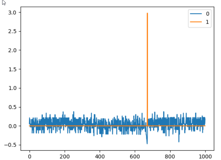
The scope looks like this (blue is current_meas_phC, orange is vel_estimate):
EDIT: Found my mistake, vel_limit was set to 2.0. I increased it to 10.0, now no error appears, but no useful rotation begins, see the following scope:
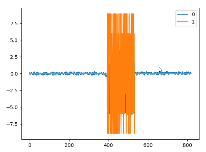
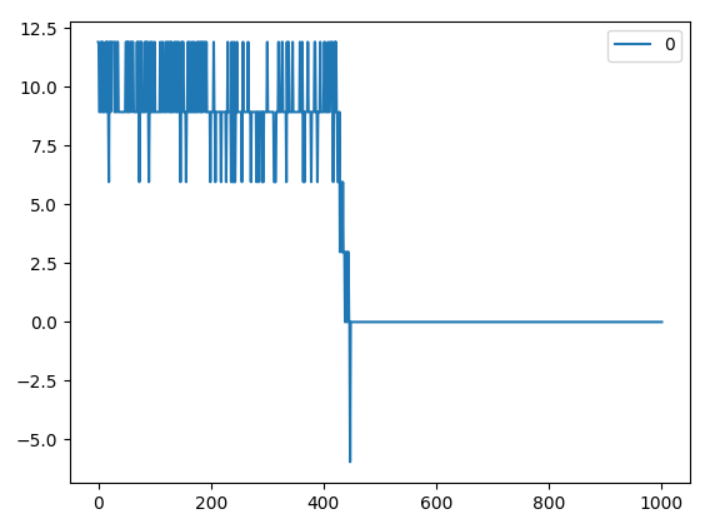
EDIT2: Now i set vel_integrator_gain = 0and vel_gain = 0.01, now it is rotating, a little bit noisy and the scope looks like this:
The velocity signal looks very strange, is it only because of the low hall sensor resolution? It looks like it only has plain values of 3, 6, 9 and 12 (when i increase velocity). So only multiples of three, no “float” values, that is strange isn’t it? Scope was recorded with ìnput_vel = 5`
EDIT3: now when i brake the motor with my hand, somehow there was the following situation:
the vel_estimate is negative, although i am 100% percentage shure the motor was still rotating in positive direction… so clearly something is wrong with encoder signal
Not exactly, no… If you let the motor move in torque mode, it should not produce any error at all. It should carry on producing that torque however you move it.
If you let go of it and it spins out of control, then you can expect to see the ERROR_OVERSPEED.
But other than that, there should be no reason for it to produce errors in torque mode, and the fact that it does, means you still have a pretty fundamental problem, most likely with your Hall sensor.
I would ignore the issues in velocity mode for now, because torque mode still isn’t behaving properly. 
hmm ok thanks… in the meantime i added the capacitors to the hall Signals, i only had 100nF but i think for the lower speeds that should work? I also received another Motor including Hall Sensor today, i will try that on monday.
It’s not to do with the speed if the motor, but the speed of the signal edges with respect to the sampling speed of the encoder input. If the capacitance is too high, it could cause ERROR_ILLEGAL_HALL_STATE. But 100nF is not too far away from 22, it should be ok.
Good luck 
Hi together,
today i am trying to get another motor running, this one. When i start full calibration, i get the ERROR_PHASE_RESISTANCE_OUT_OF_RANGE error. When i look it up, i see the following values:
calibration_current = 10.0 (float)
resistance_calib_max_voltage = 2.0 (float)
phase_inductance = 4.0044971683528274e-05 (float)
phase_resistance = 0.08224697411060333 (float)
torque_constant = 0.10337500274181366 (float)
When i measure resitance with my (cheap) multimeter, i measure 0.5 Ohm between all three phases…
What am i doing wrong again?  Thank you very much for your help!!