Odrive and Java

Disclaimer: This post is a way for me to document my progress communicating with the ODrive from Java. Maybe it will help somebody later on.

The basis of my control setup is java, so I need to find a way to communicate with the ODrive from Java. A number of options I considered:

  1. Connecting through Serial
  2. Calling Python code from Java.
  3. Accessing ODrive directly through USB.

Serial
I have earlier experience communicating over serial. However, from what I have read on this forum the serial protocol is not very stable, nor the preferred method of communicating with the ODrive.

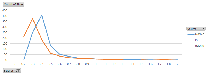
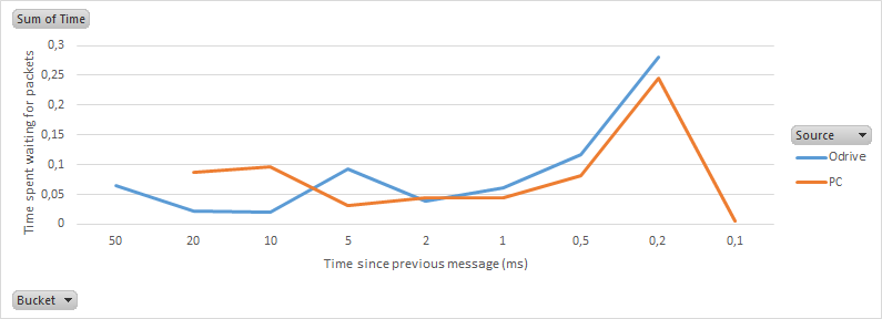
Also I hope my control loop can run at 1kHz, and I think this will be an issue over the current serial implementation. I can probably make it work at 100Hz, but faster would really be nice. At any speed my PC will need to read as many values as possible (two at the least) and send one value to the ODrive.

So i have decided against this option.

Calling Python from Java
This seems like an interesting route since the Odrivetool was written in Python. However, going from Java to Python to C++ seems very circuitous, and could make things difficult to maintain.

Accessing ODrive directly through USB
This is the option I am now exploring. It is made a lot easier by looking at the code in https://github.com/madcowswe/ODrive/blob/master/Firmware/fibre/python/fibre/ . But, my java is rusty, and I have never worked with the USB interface before. So please bear with me.

Connecting to device
To access the USB interface I am using usb4java.

First thing is to connect to a UsbDevice. According to the code below I should be looking for a device with one of three possible combinations of prodId and vendorId.

# Currently we identify fibre-enabled devices by VID,PID
# TODO: identify by USB descriptors
WELL_KNOWN_VID_PID_PAIRS = [
(0x1209, 0x0D31),
(0x1209, 0x0D32),
(0x1209, 0x0D33)
]

lines 13-19 of usbbulk_transport.py

That works quite well, and i succesfully connect to:

Product: ODrive 3.5 CDC Interface
Device info: Bus 002 Device 007: ID 1209:0d32
Manufacturer: ODrive Robotics
Serial number: 386837583437

Choosing an interface
Having chosen a device I now need to select an interface. The python code appears to have two possible preferences.

custom_interfaces = [i for i in self.cfg.interfaces() if i.bInterfaceClass == 0x00 and i.bInterfaceSubClass == 0x01]
cdc_interfaces = [i for i in self.cfg.interfaces() if i.bInterfaceClass == 0x0a and i.bInterfaceSubClass == 0x00]

So either Class 0 Subclass 1 or Class 10 Subclass 0. There are 3 available:

Interface 0, Class 2 Communications, Subclass 2
Interface 1, Class 10 Data, Subclass 0
Interface 2, Class 0 Per Interface, Subclass 1

Interface 0 does not appear to be relevant based on the python code. I am not able to claim() interface 1. So I opt for interface 2.

Endpoints
The chosen interface has two endpoints, one for direction IN and one for direction OUT. I assume that I will need both so I save the handles.

0x83, EP 3, IN
0x03, EP 3, OUT

Both have maxpacketsize 64 and Transfer Type Bulk.

Sniffing
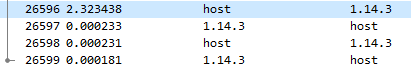
Now that I have the endpoints, I need to figure out what to send and receive. To figure out what I should be sending I am going to try sniffing the packages my python script sends. Having a working python script, and reverse engineering the packages, seems like a nice complement to reading the code (since I have trouble following the code in fibre at this point).

My Python test script is:

1 - odrv0 = odrive.find_any()
2 - print(str(odrv0.vbus_voltage))

The first message that is sent between the ODrive and my script seems to be from PC to ODrive over Endpoint 0x03, EP 3, OUT. The packet and my understanding of it are as follows:

0000 1b 00 00 37 e7 37 8e c3 ff ff 00 00 00 00 09 00
0010 00 01 00 01 00 03 03 0c 00 00 00 81 00 00 80 00
0020 02 00 00 00 00 01 00

Of which only this part is actual package data.

1 - 81 00 00 80 00 02 00 00 00 00 01 00

I have included a number at the beginning to indicate the sequence of messages. In the following packages sent to the ODrive (3 - 9) this part barely changes.

3 - 82 00 00 80 00 02 1e 00 00 00 01 00
5 - 83 00 00 80 00 02 3c 00 00 00 01 00
7 - 84 00 00 80 00 02 5a 00 00 00 01 00
9 - 85 00 00 80 00 02 78 00 00 00 01 00

Looks like some kind of acknowledgement. Lets take a look at what the ODrive is sending back. Packet 2 contains the following package data:

2 - 81 80 5b 7b 22 6e 61 6d 65 22 3a 22 22 2c 22 69 64 22 3a 30 2c 22 74 79 70 65 22 3a 22 6a 73 6f

Which when converted to ASCII is:

2 - [{“name”:"",“id”:0,“type”:“jso
4 - n”,“access”:“r”},{“name”:“vbus
6 - _voltage”,“id”:1,“type”:"float

This exchange goes one for quite a while. So it looks like the ODrive is explaining how it’s data is configured (in json).

That’s as far as I got today.

2 Likes

Now that I can see the ODrive communicating, I am going to try replicating from Java what the ODrive script is sending. This will help me understand the communication protocol.

Voltage status
By requesting the voltage status a number of times from python I can get a feel for what is sent and what is received. After connecting I ask for the odrv0.vbus_voltage three times.

print(str(odrv0.vbus_voltage))
24.0176525
print(str(odrv0.vbus_voltage))
24.0482674
print(str(odrv0.vbus_voltage))
24.0635738

That results in the following communication:

OUT 1 - b6 03 01 80 04 00 f3 c9
IN 2 - b6 83 27 24 c0 41
OUT 3 - b7 03 01 80 04 00 f3 c9
IN 4 - b7 83 da 62 c0 41
OUT 5 - b8 03 01 80 04 00 f3 c9
IN 6 - b8 83 33 82 c0 41

It looks like the first byte [or two?] is some kind of message sequence number. This appears to correspond with protocol.py line 344.

seq_no = struct.unpack(’<H’, packet[0:2])[0]

After that the OUT messages are always 03 01 80 04 00 f3 c9 which must be some kind of address location. The IN messages should correspond to something around 24.05 ± 0.05V. But which encoding is used?

83 27 24 c0 41
83 da 62 c0 41
83 33 82 c0 41

It took me a few guesses, but I found it. The most logical way to define 24.0xxxxx is as a floating point. Floats have 4 bytes, and two common significant byte orders ABCD and DCBA. By dropping the first byte, and assuming that the least significant byte is sent first (DCBA), I get the expected values.

27 24 c0 41 - 24.0176525
da 62 c0 41 - 24.0482674
33 82 c0 41 - 24.0635738

That’s great.

First messages through java
Now that I have a basic understanding of what is being sent and received, I can copy this into my java program. I decided to use the usb4java library. First I connect to my ODrive:

// Get the USB device
short vendorId = 4617;
short productId = 3378;

UsbServices services = UsbHostManager.getUsbServices();
UsbHub rootHub = services.getRootUsbHub();
UsbDevice device = UsbHighLevel.findDevice(rootHub, vendorId, productId);

And function findDevice.

public static UsbDevice findDevice(UsbHub hub, short vendorId, short productId)
{
    for (UsbDevice device : (List<UsbDevice>) hub.getAttachedUsbDevices())
    {
    	if (device.isUsbHub()) {
    		UsbDevice temp = findDevice((UsbHub) device, vendorId, productId);
    		if (temp != null) return temp;
    	} else {
	        UsbDeviceDescriptor desc = device.getUsbDeviceDescriptor();
	        System.out.println("Vendor: "+desc.idVendor()+", Product: "+desc.idProduct()+".");
	        if (desc.idVendor() == vendorId && desc.idProduct() == productId) return device;
	        if (device.isUsbHub())
	        {
	            device = findDevice((UsbHub) device, vendorId, productId);
	            if (device != null) return device;
	        }
    	}
    }
    return null;
}

Then I get the third interface (“Interface 2, Class 0 Per Interface, Subclass 1”):

UsbInterface usbInterface = (UsbInterface) device.getActiveUsbConfiguration().getUsbInterfaces().get(2);

From the interface I collect the two endpoints:

HashMap<Byte, UsbEndpoint> endPoints = new HashMap<Byte, UsbEndpoint>();
Iterator<UsbEndpoint> it = usbInterface.getUsbEndpoints().iterator();
while (it.hasNext()) {
	UsbEndpoint endPoint = it.next();
	endPoints.put(endPoint.getDirection(), endPoint);
}

Finally I send the message we intercepted earlier, and print the response in hex. Note I set the message sequence number to 0, hence the leading 00 instead of b7/b8/b9:

byte[] buffer = hexStringToByteArray("000301800400f3c9");

syncWritePacket(endPoints.get(javax.usb.UsbConst.ENDPOINT_DIRECTION_OUT), buffer);
System.out.println("Buffer write ("+System.currentTimeMillis()+"): "+bytesToHex(buffer));

buffer = syncReadPacket(endPoints.get(javax.usb.UsbConst.ENDPOINT_DIRECTION_IN));
System.out.println("Buffer read ("+System.currentTimeMillis()+"): "+bytesToHex(buffer));

The response is as expected, with a bunch of trailing 0’s that I have removed here:

Buffer write (1546260147951): 000301800400F3C9
Buffer read (1546260147952): 00832724C041

Where “2724C041” equals to 24.0176525V according to this website. The functions I call are:

private static byte[] syncReadPacket(UsbEndpoint ep) throws Exception{
	UsbPipe pipe = ep.getUsbPipe();
	byte[] buffer = new byte[ep.getUsbEndpointDescriptor().wMaxPacketSize()];
	pipe.open();
	pipe.syncSubmit(buffer);
	pipe.close();
	return buffer;
}

private static void syncWritePacket(UsbEndpoint ep, byte[] message) throws Exception{
	UsbPipe pipe = ep.getUsbPipe();
	pipe.open();
	pipe.syncSubmit(message);
	pipe.close();
}

public static byte[] hexStringToByteArray(String s) {
    int len = s.length();
    byte[] data = new byte[len / 2];
    for (int i = 0; i < len; i += 2) {
        data[i / 2] = (byte) ((Character.digit(s.charAt(i), 16) << 4)
                             + Character.digit(s.charAt(i+1), 16));
    }
    return data;
}

private final static char[] hexArray = "0123456789ABCDEF".toCharArray();
public static String bytesToHex(byte[] bytes) {
    char[] hexChars = new char[bytes.length * 2];
    for ( int j = 0; j < bytes.length; j++ ) {
        int v = bytes[j] & 0xFF;
        hexChars[j * 2] = hexArray[v >>> 4];
        hexChars[j * 2 + 1] = hexArray[v & 0x0F];
    }
    return new String(hexChars);
}

Building the first packet
To move on I would like to understand how the packets are made. As an example I will look at the first message sent from my PC that ellicits the configuration response.

81 00 00 80 00 02 00 00 00 00 01 00

By debugging the Python code it turns out that the first 6 bytes are prefaced onto the real message.

packet = struct.pack(’<HHH’, seq_no, endpoint_id, output_length)

line 278 of protocol.py

It converts the three variables, seq_no, endpoint_id, and output_length to unsigned shorts (2 bytes) with little-endian notation.

seq_no = int 129 = 81 00
endpoint_id = int 32768 = 00 80
output_length = int 512 = 00 02
81 00 00 80 00 02

After this preface the actual message is added:

00 00 00 00

Finally, a suffix is added to the message. The number 1 converted to an unsigned short with little-endian notation.

trailer = PROTOCOL_VERSION = 1
packet = packet + struct.pack(’<H’, trailer)
01 00

line 287 in protocol.py

Bringing the complete message to:

81 00 00 80 00 02 + 00 00 00 00 + 01 00

Building the other packets
After the first message is sent by the PC, the ODrive starts sending its configuration packages. After every message sent by the ODrive the PC sends an acknowledgement:

3 - 82 00 00 80 00 02 1e 00 00 00 01 00
5 - 83 00 00 80 00 02 3c 00 00 00 01 00
7 - 84 00 00 80 00 02 5a 00 00 00 01 00
9 - 85 00 00 80 00 02 78 00 00 00 01 00

Clearly the first byte is a sequence number. But the message also appears to be changing.

1e 00 00 00
3c 00 00 00
5a 00 00 00
78 00 00 00

After some more digging, it turns out this is the size of the data buffer received, so far.

buffer = bytes()
while True:
chunk_length = 512
chunk = self.remote_endpoint_operation(endpoint_id, struct.pack("<I", len(buffer)), True, chunk_length)
print("IN: "+chunk.hex())
if (len(chunk) == 0):
break
buffer += chunk
return buffer

lines 331-340 of protocol.py

Each reply from the ODrive contains 60 bytes - 30 ASCII characters. So the message should contain a number increasing in steps of 30 or 60. If we assume the number is encoded in INT32 - Little Endian (DCBA), then it makes sense.

00 00 00 00 - 0
1e 00 00 00 - 30
3c 00 00 00 - 60
5a 00 00 00 - 90
78 00 00 00 - 120

Hi,

You are doing very Nice work right here!

Cheers

Carelsbergh Stijn

Repo
I have created a repo with the files - https://github.com/riewert/JODrive.

At this stage my Java file works, and I could simply send the exact byte code messages that python generates and decode the results in Java. However it seems worth understanding the protocol a little better, so that messages can be generated directly from the configuration that was loaded into java.

Requesting values
Now that I have the configuration loaded into my program I need to understand how to request values. To test this I am going to request a few different values through Python. First the vbus_voltage.

print(str(odrv0.vbus_voltage))

OUT: ab02 0180 0400 f3c9
IN: ab82 da62 c041
24.048267364501953

In the configuration it is defined as:

[...{
    "access": "r",
    "name": "vbus_voltage",
    "id": 1,
    "type": "float"
}...]

So from what I understand of the code, these packages follow the same encoding principle as the configuration requests. Meaning there is a prefix, a message content, and a suffix.

seq_no + endpoint_id + output_length + message_content + trailer

SEQ_NO - the seq_no is 555 but 128 (0x80) is always added, so 683 - ab02
ENDPOINT_ID - the endpoint_id is 1 but 32768 (0x8000) is always added if a reply is requested, so 32769 - 0180
OUTPUT_LENGTH - int 4 - 0400
MESSAGE_CONTENT - empty
CRC16 - int 51699 - f3c9
ab02 0180 0400 EMPTY f3c9

I’m not sure, but I don’t think the USB algorithm allows more than four 0-bytes to be sent in a row. That is why 0x80 is added to the seq_no. Also I haven’t looked into the crc16 value yet. I probably will later.

The next request I would like to understand, appears to send two messages.

print(str(odrv0.axis0.get_temp()))

OUT: ad02 3f80 0000 f3c9
IN: ad82
OUT: ae02 4080 0400 f3c9
IN: ae82 fe1f df41
27.890621185302734 [=fe1f df41]

Assuming the messages are constructed with the same function I should be able to understand them.

Message 1

SEQ_NO - ad02 - (685 - 128) = 557
ENDPOINT_ID - 3f80 - (32831 - 32768) = 63
OUTPUT_LENGTH - 0000 = 0
MESSAGE_CONTENT - EMPTY
CRC16 - f3c9 - 51699

Message 2

SEQ_NO - ae02 - (686 - 128) = 558
ENDPOINT_ID - 4080 - (32832 - 32768) = 64
OUTPUT_LENGTH - 0400 = 4
MESSAGE_CONTENT - EMPTY
CRC16 - f3c9 - 51699

Looking at the configuration this seems to make sense.

  {
    "outputs": [
      {
        "access": "rw",
        "name": "result",
        "id": 64,
        "type": "float"
      }
    ],
    "inputs": [],
    "name": "get_temp",
    "id": 63,
    "type": "function"
  },

So from the looks of things, it first calls the function get_temp on the ODrive. Then when this function has completed successfully, it calls result (which surprisingly can also be written to).

This gives me enough insight to complete my Java library. Tomorrow.

Performance
So i am now reading values quite consistently. When I read the value “vbus_voltage” 1000 times I am seeing an average of 1.5ms ± 0.5ms for request and reply. I have no other devices connected to the USB port, and 95% of the time is taken up by the library reading or writing from the port. So this appears to the be fastest I can get it to work.

I recorded one of my tests in Wireshark and measured the time between messages. In general the median time the PC takes send a new request after a message from the ODrive is 0.3ms. The median time it takes the ODrive to reply to a request is 0.4ms.

In total this trace contains 2000 message (1000 requests and 1000 replies) and takes a total of 1.3 seconds.

This means that there are quite a few outliers causing the average to rise. By summing the times this becomes more apparent.

I think the most likely cause is Java garbage collection.

Async
I have tried sending a message to the ODrive with an asynchronous request, but haven’t been able to see any replies. For now I am assuming this has not been implemented yet in the ODrive firmware 4.7. [I got this working on the PC side, but it didn’t provide a significant increase in performance].

So I have done some testing now that I have 3-odrives functioning properly. With all three connected to a single USB-3 HUB I am seeing approximately 4.0ms ± 1ms for request and reply. The latency appears to scale linearly with the number of ODrives connected. Also the USB-3 hub does not provide any advantages over a normal hub.

Apparently USB-2 hubs sometimes have an MTT chip, which translates USB-1.1 into USB-2. Does anybody have experience using multiple ODrives over an MTT hub? I expect it would improve the latency when multiple ODrives are connected.

MTT USB2 Hub

Reading multiple values simulateously

For each position I want to read the encoder position and a GPIO value as fast as possible. Requesting each value individually is too slow, so I am exploring alternatives.

Today I will try to modify the firmware so that is sends the values I need after a single request.

In communication.cpp line 186 I added the following lines:

make_protocol_object("custom_values",
        make_protocol_property("axis0_pos", &axes[0]->encoder_.pos_estimate_),
        make_protocol_property("axis1_pos", &axes[1]->encoder_.pos_estimate_)
)

This gives me the following behaviour:

image

So that works. Looking at the trace captured by wireshark it is still sending individual packets, but it does look like they are processing very fast.

image

Round trip for two values, is about 0.5ms. (It also looks like the Odrivetool is a lot faster than my java program, which is encouraging.)

Multiple values in a single message - DIDN’T WORK
The next thing I am going to try, is packaging multiple values into a single packet. To do this I modified communication:187 to:

make_protocol_object("custom_values",
    make_protocol_property("axis0_pos", &axes[0]->encoder_.pos_estimate_),
    make_protocol_property("axis1_pos", &axes[1]->encoder_.pos_estimate_),
    make_protocol_function("positions", static_functions, &StaticFunctions::positions)
)

Then to communcation:113 I added:

std::tuple<float, float> positions() {return {axes[0]->encoder_.pos_estimate_, axes[1]->encoder_.pos_estimate_};}

And finally to protocol:403 I added:

template<>
inline constexpr const char* get_default_json_modifier<std::tuple<float, float>>() {
    return "\"type\":\"array\",\"items\":{\"type\":\"float\"},\"access\":\"r\"";
}

But that doesn’t work, looks like more stuff needs to be modified, but I’m not sure what.

GPIO values

Next step is to add GPIO values. These are usually called from a function, which makes them harder to add.

In communication:113 I added:

float get_GPIO_3() { return get_adc_voltage(get_gpio_port_by_pin(3), get_gpio_pin_by_pin(3)); }
float get_GPIO_4() { return get_adc_voltage(get_gpio_port_by_pin(4), get_gpio_pin_by_pin(4)); }

And I changed communcation:187 to:

make_protocol_object("custom_values",
    make_protocol_property("axis0_pos", &axes[0]->encoder_.pos_estimate_),
    make_protocol_property("axis1_pos", &axes[1]->encoder_.pos_estimate_),
    make_protocol_function("GPIO_3", static_functions, &StaticFunctions::get_GPIO_3),
    make_protocol_function("GPIO_4", static_functions, &StaticFunctions::get_GPIO_4)
 )

But that doesn’t work, because I still need to call the functions individually to get the results.

image

The function get_adc_voltage() converts the raw ADC reading into a voltage reading. Voltage = raw_value * 3.3 / 4096. Luckily I can access the raw value and return that directly with a small change:

make_protocol_property("GPIO_3", &adc_measurements_[3]),
make_protocol_property("GPIO_4", &adc_measurements_[4])

And that appears to work nicely:

image

Though appearantly GPIO 3 & 4 are mapped to pin 2 and 3.

1 Like

Since an make_protocol_object does not have an end-point I need to make a different request to the odrive than previously. The conversation between the Odrivetool and the odrive is as shown below:

image

OUT - ae03 8981 0400 7321
IN - ae83 0200 0040
OUT - af03 8a81 0400 7321
IN - af83 0000 803e
OUT - b003 8b81 0200 7321
IN - b083 4f0e
OUT - b103 8c81 0200 7321
IN - b183 e20d

Assuming the same structure still applies the first sent message is probably:

SEQ_NO - ae03 - (942 - 128) = 814
ENDPOINT_ID - 8981 - (33161 - 32768) = 393
OUTPUT_LENGTH - 0400 = 4
CRC16 - 7321 = 8563

And looking at the configuration this is the endpoint_id for the first member of custom_values, which is the id for the location of the axis:

{
	"members": [
		{
			"access": "rw",
			"name": "axis0_pos",
			"id": 393,
			"type": "float"
		},
		{
			"access": "rw",
			"name": "axis1_pos",
			"id": 394,
			"type": "float"
		},
		{
			"access": "rw",
			"name": "GPIO_3",
			"id": 395,
			"type": "uint16"
		},
		{
			"access": "rw",
			"name": "GPIO_4",
			"id": 396,
			"type": "uint16"
		}
	],
	"name": "custom_values",
	"type": "object"
}

I had hoped my PC was only replying with ACKs, but appearantly it is still sending a request for each item. This means that this modification is probably not any faster than simply requesting each value individually.

Great work!
A Java programmer myself. However for my current project I see no need for this as I am going to interface Odrive from a Teensy (arduino). So I will need to build a GUI for that platform instead and the teensy-odrive communication is then low level. However, you work may form a basis for that nevertheless, especially as a form of communication docs (in code).

Sounds cool. I thought about doing that, for my application I need to control at least 6-odrives. So I would need two teensy’s I think. They add an extra control layer (complexity + weight), so I wanted to try this avenue first.

Combine everything into one variable

I am not satisfied with the solutions I’ve tried so far. Time for a different approach, try and fit my variables into the biggest variable I (think I) can send over in a single message.

The biggest thing I can find in fiber and/or the odrive firmware is the uint64 of 8 bytes. The variables I want to send are:

GPIO3 - Log2(4096) = 12 bits = 1.5 bytes
GPIO4 - Log2(4096) = 12 bits = 1.5 bytes
axis0.encoder.pos_estimate - float = 32 bits = 4 bytes
axis1.encoder.pos_estimate - float = 32 bits = 4 bytes

For a total of 11 bytes. To fit that into 8 bytes I’m going to need to drop some bytes, and the most logical place for me is the position estimates. Mechanically my motor is constrained to positions 0 and 1500, and my (hall) encoders cannot measure with higher accuracy than 1 position point.


When I manually move the motor one step, I see that there are some nummerical errors being introduced, if I round these values I will loose some data.

In [40]: odrv1.axis1.encoder.pos_estimate
Out[40]: 1498.765625

In [41]: odrv1.axis1.encoder.pos_estimate
Out[41]: 1498.765625

In [42]: odrv1.axis1.encoder.pos_estimate
Out[42]: 1499.0

In [43]: odrv1.axis1.encoder.pos_estimate
Out[43]: 1500.765625

In [44]: odrv1.axis1.encoder.pos_estimate
Out[44]: 1499.0

In [45]: odrv1.axis1.encoder.pos_estimate
Out[45]: 1500.765625

To account for this I would like to send a resolution of at least 16 times higher than my total position range. Taking a safety margin I will assume a range of -500 - 2500 = 3000. Then my resolution must be 3000*16 = 48000 which equates to Log2(48000) = 15.5 bit, rounded up to 16 bits or 2 bytes which matches nicely with a uint16.

To convert pos_estimate to a uint16 I will use the following formula:

pos_to_send = (pos_estimate + 500) * 65535/3000

I have spent the last few weeks searching for a way to return a 64bit value. When I implemented my ideas, the firmware wouldn’t compile. I was encountering an interal compiler error whenever I created a function that returned 64bits. To solve the issue I changed to gcc 9.1, arm-none-eabi-gcc 9.1, the devel branch, and ArchLinux.

Resulting function
The first thing my function will need is input. I will be feeding it two concaternated uint16 position values.

As output I will define the two GPIO values and the current encoder positions.

Having both these inputs and outputs means I will only need to send one message to the ODrive to get all the information I need. In the future I might add error codes.

uint64_t set_positions_get_positions(uint32_t in_positions){
    pos_1_buffer = ((uint16_t) (in_positions >> 16))*3000.0/65535.0-500.0;
    pos_2_buffer = ((uint16_t) (in_positions & 0x0000FFFF))*3000.0/65535.0-500.0;
    axes[0]->controller_.move_to_pos(pos_1_buffer);
    axes[1]->controller_.move_to_pos(pos_2_buffer);

    out_buffer = 
        (((uint64_t) &adc_measurements_[2]) << 44) + // last bit at 56.
        (((uint64_t) &adc_measurements_[3]) << 32) +
        (((uint64_t) ((axes[0]->encoder_.pos_estimate_+500.0) / 3000.0 * 65535.0)) << 16) +
        (((uint64_t) ((axes[1]->encoder_.pos_estimate_+500.0) / 3000.0 * 65535.0)));
    return out_buffer;
}

This way if the input is 0xffff0000 I will be setting pos1 = 2500 and pos2 = -500.

Assuming the axes are already at these positions, and GPIO3 = 3.2V = 4095 (&adc_measurements_[2]) and GPIO4 = 0V = 0 (&adc_measurements_[3]) the output of the function will be 0xfff000ffff0000.

I am having some trouble getting my rig working, because the dupont connectors are corroding. I soldered them, instead of crimping, and used a lot of flux. >_<.

Anyways, I got my code working and it works. But something strange is going on.

When I tell it to move both axis to position 100 ((100+500)/3000*65535 = 13107 = hex(3333)) the axis move as expected. Very good news.

As an example I will send the command: odrv2.set_positions_get_positions(0x31323134). These positions are axis0 = ((76.516+500)/3000 *65535 = 12594) 3132 and axis1 = ((76.608+500)/3000 *65535 = 12596) 3134. However when I look at the usb-trace something weird is happening:

OUT: 9304 8c81 0000 3431 3231 d153
IN: 9384
OUT: 9404 8b81 0000 d153
IN: 9484
OUT: 9504 8d81 0800 d153
IN: 9584 1031 1531 4ec9 9420

First, we see that the byte orders are switched arround (3431 instead of 3134). This is because the transfer protocol changes the Endianness of the message. It does not cause a problem. We can confirm this by checking that odrv2.axis1.controller.pos_setpoint is set correctly to 76.608.

Breaking down the first message:

SEQ_NO - 9304 -
ENDPOINT_ID - 8c81 - (33164 - 32768) = 396
OUTPUT_LENGTH - 0000 = 0 - strange
MESSAGE_CONTENT - 3431 3231 - correct just a different encoding
CRC16 - d153

After this message, we see a sequence of empty responses, and requests between my PC and the ODrive, until finally the message:

SEQ_NO - 9584 -
MESSAGE_CONTENT - 1031 1531 4ec9 9420

Again the bytes are all mixed up, but 3110 (12560 * 3000 / 65535 -500 = 74.96) and 3115 (12565/65535 * 3000 - 500 = 75.19) seem like realistic position values. I will check the GPIO values later.

It took a while, but with a lot of help (from @Samuel and @Wetmelon), I was able to further compress the amount of messages sent.

Now the usb-trace is:

OUT: 8900 0180 1800 9c14 2741 2b57 0d41 0c39
IN: 8980 0000 10be 0000 0000 335f e93f 0000 e2bf 0000 0000 66ea bf3f

Where the first message is:

SEQ_NO - 8900 -
ENDPOINT_ID - 0180 - (X - 32768) = 396
OUTPUT_LENGTH - 1800 = 24
MESSAGE_CONTENT - 9c14 2741 2b57 0d41 - 2x (2 bytes for desired position)
CRC16 - 0c39

And the return message is:

SEQ_NO - 8980 -
MESSAGE_CONTENT - 0000 10be 0000 0000 335f e93f 0000 e2bf 0000 0000 66ea bf3f 
                - 2x (2 bytes for current position, 2 bytes for current velocity, 2 bytes for gpio)

Most of the relevant changes were added in this commit: https://github.com/riewert/ODrive/commit/a46133b653108cd6771f53a6f15fd2beb275f462 . They will probably be obsolete when fibre gets updated, but until then it might be useful to others.

I haven’t been able to run any tests on performance yet, but it is looking pretty good.