ODrive Browning Out Suspection

Hi,

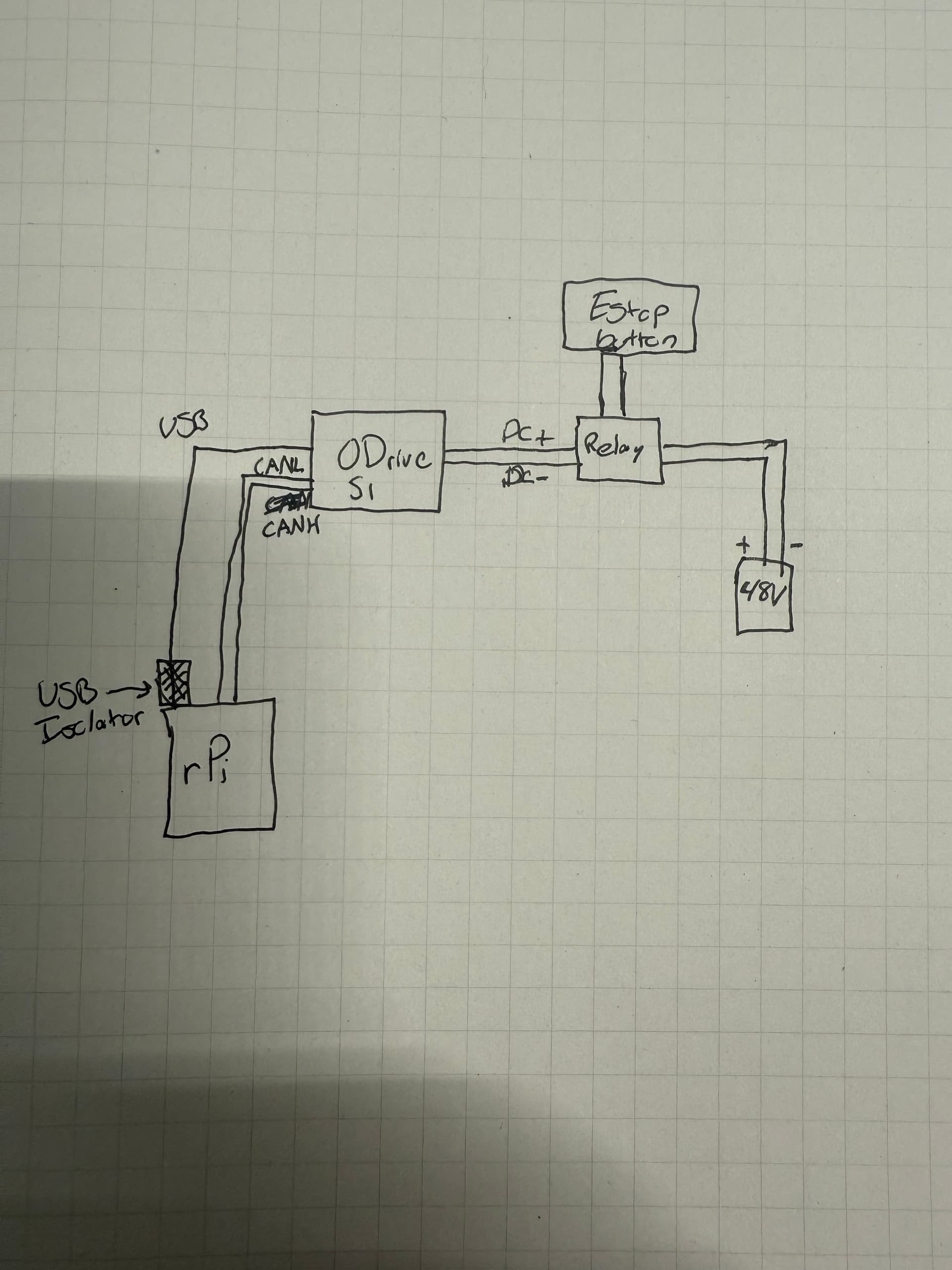
I am currently having an issue with my S1 that I suspect is a “browning out” problem. During use, sometimes connectors get jostled the wrong way which causes power to not be fully delivered via USB-C from my Raspberry Pi. This causes the ODrive to repeat the previously sent command until I kill the system with an E-Stop. The message I get in the middle of the control loop has arbitration ID 0x04, instead of 0x09, and when I try reading the message the same way I do in closed loop mode, get_encoder_estimates reads (-2.86e-42,0) for motor position and velocity (note the first number is usually just any very small number). It seems as if the motor loses itself and spins indefinitely unless I cut power myself. Upon rebooting, I check for a heartbeat and do not get one until I reset the connection between my Raspberry Pi and ODrive, the power cycling always seems to do the trick.

I try to send a message over the CAN bus, but since the connection has been effectively severed during that moment, the message is not received.

I guess my questions is twofold: am I correct this is some browning out error? If so, I was wondering if there was some functionality I might be able to implement where if this were to occur, the motor should shut down. On top of better securing my connectors, I was wondering if there could be a better absolute failsafe option.

Thanks so much,
Dom

“fully delivered via USB-C from my Raspberry Pi”

Do you mean that the rPi is browning out? Or that the S1 is being powered over USB from the Pi, and the connection is being knocked?

am I correct this is some browning out error?

I don’t think so, if the S1 is connected via DC+ power as well, then it’ll draw from that, doesn’t need USB.

On top of better securing my connectors, I was wondering if there could be a better absolute failsafe option.

You can always enable the watchdog, we recommend that.

All that being said, this generally shouldn’t happen. The expected behavior is that when the CAN connection is restored, the ODrive continues sending heartbeats/other periodic messages typically. Maybe you have autobaud set, and the ODrive is dropping back into scanning mode due to the bus-off detection?

Some questions:

  1. What CAN adapter are you using for the Pi?
  2. Does this still happen when the S1 is unplugged over USB-C and only powered from DC+?
  3. Can you send a few pictures of your wiring?

Hi,

  1. This is the CAN Hat I am using: https://www.waveshare.com/2-ch-can-hat.htm

  2. Maybe I set this up wrong, but the ODrive does not display anything from the LED unless I have the Raspberry Pi plugged into it as well. I do not see a cyan LED color when the power is being delivered to the ODrive unless the USBC is plugged into the ODrive at the same time. I power the S1s with 2 6s LiPo batteries. Any idea why this might be happening?

  3. I attached a drawing of the wiring because it is quite a messy setup currently so pictures do little to help. Let me know if you require more pictures and I will try to take some informative ones. The rPi is directly connected to wall power. We have the drives powered by the battery and the rPi isolated from that.

For various predetermined reasons the system i am using runs realtime on a Pi, and the code is quite heavy, so the loop rate is variable. I have setup the ODrive to not send cyclic messages, but instead explicitly send/receive when prompted. Also, I am running on firmware 0.6.9.post0. Watchdog is not enabled (I think because I don’t have cyclic messages on?), and autobaud should not be enabled because I am on an older firmware.

Maybe I set this up wrong, but the ODrive does not display anything from the LED unless I have the Raspberry Pi plugged into it as well. I do not see a cyan LED color when the power is being delivered to the ODrive unless the USBC is plugged into the ODrive at the same time. I power the S1s with 2 6s LiPo batteries. Any idea why this might be happening?

Yeah this is super abnormal. Do you think you might be shorting the 5V rail somehow? Does it still do this when you disconnect everything (except the power) from the S1?

I’m unsure how I could be shorting that rail, unless hitting the EStop during use caused some kind of issue? The relay I have set up is meant to sink a lot more current than we could ever pull. Just checked, and this does happen even when everything is disconnected except for battery power.

Also should note I have 2 identical setups as part of the same system that only share battery power. The rPis, CAN connections, and all other parts are isolated from one another. The lack of LED power happens for both systems. I don’t recall ever plugging these into the Pis without the USB isolators, so I don’t think I caused a ground loop at some point.

I’m unsure how I could be shorting that rail, unless hitting the EStop during use caused some kind of issue? The relay I have set up is meant to sink a lot more current than we could ever pull. Just checked, and this does happen even when everything is disconnected except for battery power.

What was your original order number? I’d like to swap out your S1 and see if the problem persists.

Also should note I have 2 identical setups as part of the same system that only share battery power. The rPis, CAN connections, and all other parts are isolated from one another. The lack of LED power happens for both systems. I don’t recall ever plugging these into the Pis without the USB isolators, so I don’t think I caused a ground loop at some point.

That’s very strange. I think some pictures of the wiring would be very helpful. What encoder/others do you have plugged into the S1?

If you disconnect everything from the S1 except for power (e.g. unplug USB, CAN, encoders, etc), does it still not turn on? Or does the green LED turn on but the RGB one doesn’t? Etc.

The order number was 11166

I have nothing else plugged into the S1, I use the onboard encoder and no other accessories. I attached some pictures of the setup, its a bit tough to follow but the green and white cables are the CAN wires, and then the power gets delivered through the relay from DC+ and DC- that is gated by the relay and EStop button. The other CAN connection is for intermittent messages the Pis send to each other.

EDIT: the ethernet from the Pi is to my PC so I can SSH in, and the other USB is a connection to an external microcontroller board. The ODrive is connected to the USB isolator.

I tried about everything. If I connect the batteries and run my code, when I ask the S1 for a heartbeat, nothing is returned and my code errors out. No LEDs come on at all when there isn’t any power from the Pi as far as I can tell.

Here are some pics:


Interesting. So the only way this can happen is if you nuked the 5V logic rail somehow, but the 12V gate drive rail was still OK.

Here’s something that would be super super useful:

  • Remove the S1 from the motor, disconnect CAN and USB
  • Connect DC+/DC- directly to a bench power supply via the screw terminals (so we don’t have to worry about any soldering issues with your connectors).
  • Give it about 24V from the bench supply at some nominal safe current limit - maybe 0.1-0.5A.
  • Check what the reported current output is from the bench supply. Should be something like 0.01-0.05A.
  • Measure the following test points (on the back of the board). All measurements can be done relative to DC-
  • T7, T8, T9, T10, T30, T31, T12, T13, T1

Diagram below w/ test points marked to make it easier:

Careful when measuring the test points, they’re pretty small and you don’t want your multimeter probe to slip. Once you’ve done that, please let me know the voltage at each!

I have two concerns with what I’ve seen from your pictures:

  1. You have a piece of plastic for mounting that’s sitting directly on top of the 5V regulator, marked with an arrow. This definitely makes me suspect mechanical damage.
  2. As far as I can tell, you don’t have any precharge or soft-start circuit. This means that whenever your contactor closes (connects), you’re slamming the S1s with your full bus voltage. That causes a massive inrush current, and can spike the input voltage really high (I’ve seen to 80-90V from a 48V supply with uncontrolled inrush), and cause damage. I would strongly recommend adding a second relay/contactor in parallel with the main bus one, with a ~1-2ohm resistor across it – this way when powering on the system, you can close the precharge contactor for a second or two before closing the main contactor, so that the bus voltage at the S1s can safely ramp up with managed inrush current.

Got it. I’ll follow up in this thread when I test all of those components! Thanks for your help so far!

Tested! Here are the results. The lack of 5V makes me think that the regulator is damaged.

image

I appreciate the advice about implementing a soft start circuit. I will look into adding one in to avoid this issue in the future with other drives. I am not sure if it was mechanical damage that caused this or something else, but better safe than sorry!

For future reference, what exactly are these T pins? Just so I know what I’m testing for in the future! :slight_smile:

EDIT: Also, reported current is 0.031A

EDIT2: Assuming the worst case, what wattage resistor should I be looking at for the soft start? Most datasheets report continuous, unsure of what peaks they can handle.